JVC KS-AX5102 Instruction Manual
JVC KS-AX5102 Manual
 |
View all JVC KS-AX5102 manuals
Add to My Manuals
Save this manual to your list of manuals |
JVC KS-AX5102 manual content summary:
- JVC KS-AX5102 | Instruction Manual - Page 1
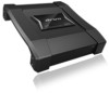
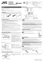
KS-AX5104 KS-AX5102 KS-AX5101D POWER AMPLIFIER: Instructions ENGLISH Thank you for purchasing a JVC product. If you have any questions or require information regarding installation kits, consult your JVC the unit since there are no user serviceable parts inside. INSTALLATION OF THE UNIT The - JVC KS-AX5102 | Instruction Manual - Page 2
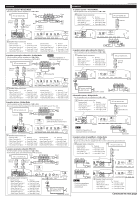
KS-AX5104 4-speaker system-Normal Mode • Use the speakers with an impedance of 2 Ω to 8 Ω. JVC car receiver, etc. Front Line out (Front) *2 Rear Line out *2 (Rear) Front Rear KS-AX5102 2-speaker system-Normal Mode • Use the speakers with an impedance of 2 Ω to 8 Ω. Speaker input connector - JVC KS-AX5102 | Instruction Manual - Page 3
R *2 Not supplied CONTROLS KS-AX5104 JVC car receiver, etc. Line out (Rear) or Subwoofer out *2 KS-AX5102 FRONT REAR KS-AX5101D R R 2-Subwoofer with the unit on, some trouble has occurred (see "TROUBLE SHOOTING"). TROUBLESHOOTING For more details, consult your JVC car audio dealer. The POWER
-
 1
1 -
 2
2 -
 3
3
 |
 |

1
KS-AX5104
KS-AX5102
KS-AX5101D
POWER AMPLIFIER: INSTRUCTIONS
1211MOHMDWKAYA
EN
© 2011 JVC KENWOOD Corporation
ENGLISH
Thank you for purchasing a JVC product.
If you have any questions or require information regarding installation kits, consult your JVC Car audio
dealers or a company supplying the kits.
For safety
....
• Stop the car before performing any complicated operations.
• Do not raise the volume level too much, as this will block outside sounds, making driving dangerous.
ACCESSORIES
...4
KS-AX5102
KS-AX5101D
KS-AX5104
...8
...1
...1
...2
CAUTIONS AND NOTES
This unit is designed to operate on
12 V DC, NEGATIVE ground electrical systems.
JVC recommends consulting a qualified technician for installation.
• This unit uses BTL (Balanced Transformerless) amplifier circuitry, i.e., floating ground system, so
comply with the following:
– Do not connect the “
·
” terminals of the speakers to each other.
– Do not connect the “
·
” terminals of the speakers to the metal body or chassis.
• Cover the unused leads with insulating tape to prevent them from short circuiting.
• When an extension lead is used, it should be as thick and short as possible; connect it firmly with
insulating tape.
• Be sure to leave an appropriate space between the antenna (aerial) and the wires of this unit.
• If the fuse blows, first make sure the wires aren’t touching to cause a short circuit then replace the old
fuse with one with the same rating.
• Do not let pebbles, sand or metallic objects get inside the unit.
• To keep the heat dissipation mechanism running effectively, wipe the accumulated dust off
periodically.
• Listening to the tape, radio, CD or digital audio player, etc. with the volume set at a high level for
a long period of time will exhaust the battery, while the engine is turned off or while the engine is
idling.
• This unit becomes very hot. Be careful not to touch the unit not only when using but after using.
• DO NOT disassemble the unit since there are no user serviceable parts inside.
INSTALLATION OF THE UNIT
The following illustration shows a typical installation. However, you should make adjustments
corresponding to your specific car.
Location of the unit
Under the front seat
Onto the trunk floor
• Mount this unit on a firm surface, such as in the
trunk or under the front seat.
• Since heat is generated in the unit, do not mount
it near inflammable objects. In addition, mount
it in an area that will not prevent the unit from
dissipating the heat.
• Do not mount the unit in the places subject to
heat: near a radiator, in a glove compartment or
in insulated areas such as under a car mat that will
prevent the unit from dissipating heat.
• When mounting the unit under the front seat, make
sure that adjusting the seat position will not catch
any wire of the unit.
Install the unit
Provided screw
φ 4 × 20 mm (
13
/
16
in.)
Drilled hole
Installation board etc.
(thickness : 19 mm or
more)
• When mounting this unit, be sure to use the
provided screws.
• If any other screws are used, there is a risk of
loosening the unit or damaging the parts under the
car floor.
• Before drilling holes in the trunk to install the unit,
make sure that there is a sufficient space under the
trunk so that you do not drill holes in the fuel tank,
etc.
INSTALLATION OF THE SIDE COVER
Provided screw
Φ 3 × 8 mm (
1
/
8
in.)
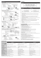
POWER SUPPLY
To metallic body or chassis*
(To an accessory terminal)
Fuse*
Car battery
Ignition switch
JVC car receiver, etc.
Remote turn-on line*
KS-AX5102
KS-AX5104
KS-AX5101D
* Not Supplied
Caution
To prevent short circuits while making connections, keep the battery’s negative terminal disconnected.
• When using a power cord (purchased separately), be sure to place the fuse near the battery as
shown.
• Connect the lead wire (power cord) through which power is supplied directly to the battery’s “
ª
”
terminal only after all the other connections have been made.
The proper lead wire connected to each POWER terminal is as follows.
• + B and GND: AWG 8 to AWG 4 (The cross section is about 8
mm
2
to 21
mm
2
.)
• REM: AWG 18 to AWG 8 (The cross section is about 0.8
mm
2
to 8
mm
2
.)
a
When you use JVC car receiver with a remote lead, connect to the REM terminal on this unit.
b
When you connect a unit without a remote lead, connect to the accessory circuit of the car which
is activated by the ignition switch. In this case, noise may occur when the car receiver is turned on
or off. To avoid this noise, do not turn on or off the car receiver itself. You can turn on or off the car
receiver along with the on/off operation of the ignition switch.
TERMINAL CONNECTIONS
When making terminal connections, properly fix each terminal with the provided screw by turning it as
illustrated.
• Use ring terminals (not provided) for secure connection.
Notes
• Make sure the screw is fixed in place to prevent disconnections.
• Avoid over-tightening as it may cause the damage to the screw or its head
slot.
SPEAKER SYSTEMS
Notes
• Be sure not to connect the “
·
” terminals of the speakers to a common point.
• If the same lead is used for both left/right or front/rear speaker wirings, this unit cannot be used.
Always use the independent leads for each speaker. In this case, redo the wirings.
• Use the speakers with an impedance of 2 Ω to 8 Ω (4 Ω to 8 Ω: when used in Bridge Mode).
• Use the speakers which have sufficient capacity to the unit.
The proper lead connected to each SPEAKER OUTPUT terminal is as follows.
KS-AX5104/KS-AX5102:
AWG 18 to AWG 12 (The cross section is about 0.8 mm
2
to 3.3 mm
2
).
KS-AX5101D:
AWG 18 to AWG 8 (The cross section is about 0.8 mm
2
to 8 mm
2
).
SPEAKER CONNECTIONS
Connection varies depending on the number of the speakers used in your car. Select the appropriate
connection referring to the following diagrams.
Notes
• Securely connect all the parts. If the connections are loose, due to contact resistance etc., heat will
break out and may cause an accident.
• Run the connection leads under the car mats to prevent accidental disconnections.
Å
When your receiver is equipped with line output.
ı
When your receiver is NOT equipped with line output.
KS-AX5104
KS-AX5102
KS-AX5101D
• Connect each lead of the speaker input connector to a speaker positive lead or negative lead of the
receiver.
For Customer Use
:
Enter below the Model No. and Serial No. which are
located on the top or bottom of the cabinet.
Retain this information for future reference.
Model No.
Serial No.
LVT2338-001A
[K]
• Attach the side cover using the provided screws
after connected speaker and power supply cables
and installed the unit.
Continued to next page
Φ4 × 20 mm
(13/16 in.)
Φ3 × 8 mm
(1/8 in.)
[European Union only]