Kenwood KDC 135 Instruction Manual - Page 17
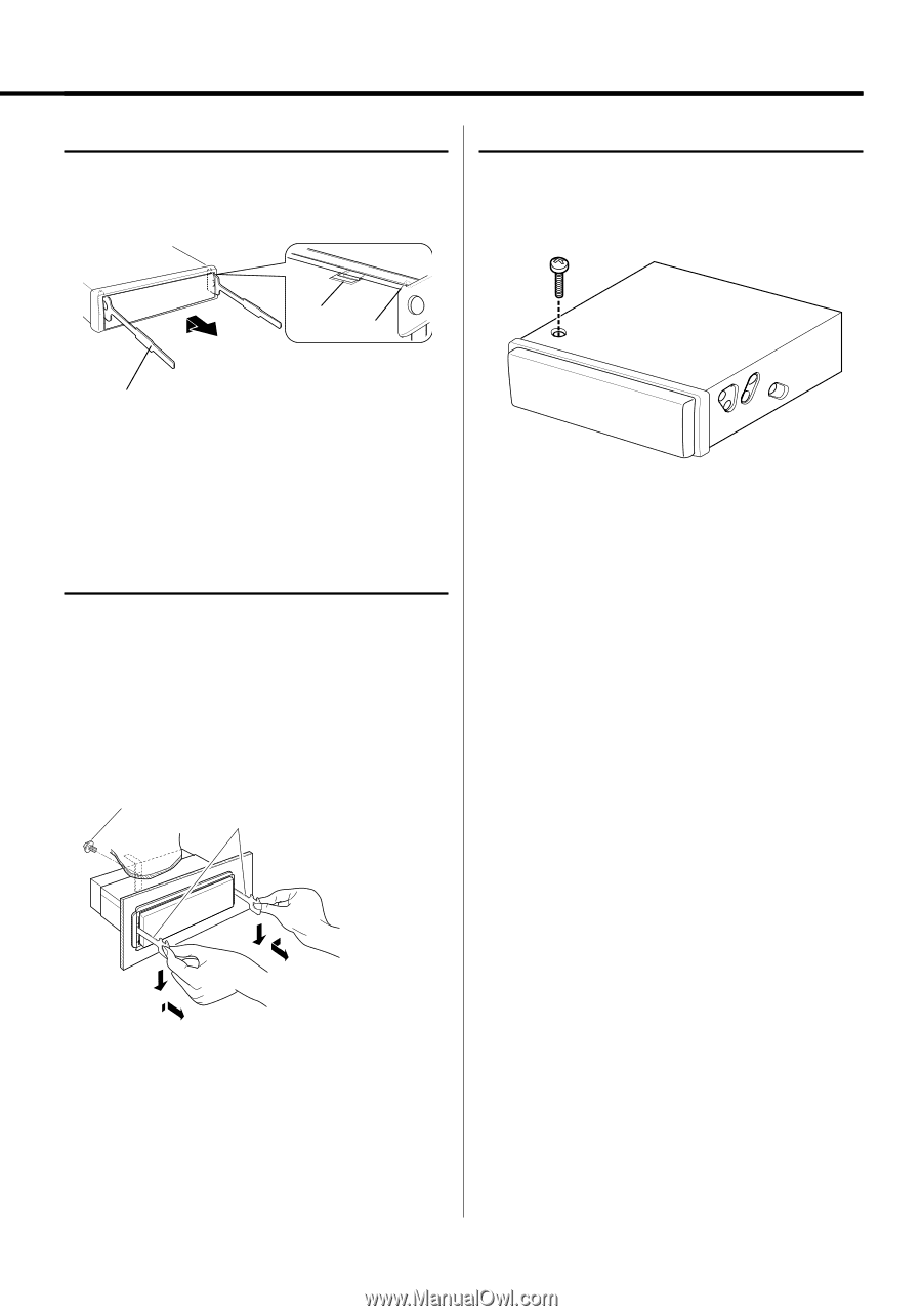
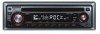
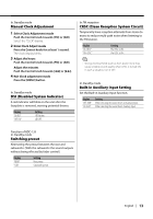
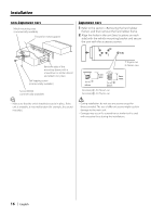
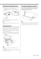
Removing the hard rubber frame, Removing the Unit, Screwing the Faceplate on the Unit
 |
UPC - 019048170088
View all Kenwood KDC 135 manuals
Add to My Manuals
Save this manual to your list of manuals |
Page 17 highlights
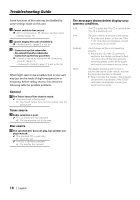
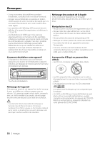
Removing the hard rubber frame 1 Engage the catch pins on the removal tool and remove the two locks on the upper level. Upper the frame and pull it forward as shown in the figure. Screwing the Faceplate on the Unit If you want to fasten the faceplate to the main unit so that it does not fall off, screw in the provided screws in the holes shown below. Accessory5 Lock Catch Accessory2 Removal tool 2 When the upper level is removed, remove the lower two locations. ⁄ • The frame can be removed from the bottom side in the same manner. Removing the Unit 1 Refer to the section and then remove the hard rubber frame. 2 Remove the screw (M4 × 8) on the back panel. 3 Insert the two removal tools deeply into the slots on each side, as shown. 4 Lower the removal tool toward the bottom, and pull out the unit halfway while pressing towards the inside. Screw (M4X8) (commercially available) Accessory2 ¤ • Never insert the screw in any other screw hole than the one specified. If you screw them in another hole, it will contact and may cause damage to the mechanical parts inside the unit. ¤ • Be careful to avoid injury from the catch pins on the removal tool. 5 Pull the unit all the way out with your hands, being careful not to drop it. English | 17
-
 1
1 -
2
-
3
-
4
-
5
-
6
-
7
-
8
-
9
-
10
-
11
-
 12
12 -
 13
13 -
 14
14 -
 15
15 -
 16
16 -
 17
17 -
 18
18 -
 19
19 -
 20
20 -
 21
21 -
 22
22 -
23
-
24
-
25
-
26
-
27
-
28
-
29
-
30
-
31
-
32
-
33
-
34
-
35
-
36
-
37
-
38
-
39
-
40
-
41
-
42
-
43
-
44
-
45
-
46
-
47
-
48
-
49
-
50
-
51
-
52
-
53
-
54
-
55
-
56
 |
 |