Kenwood TS-570D User Manual - Page 67
Rtty Equipment, Linear Amplifier, Antenna Tuner
 |
View all Kenwood TS-570D manuals
Add to My Manuals
Save this manual to your list of manuals |
Page 67 highlights
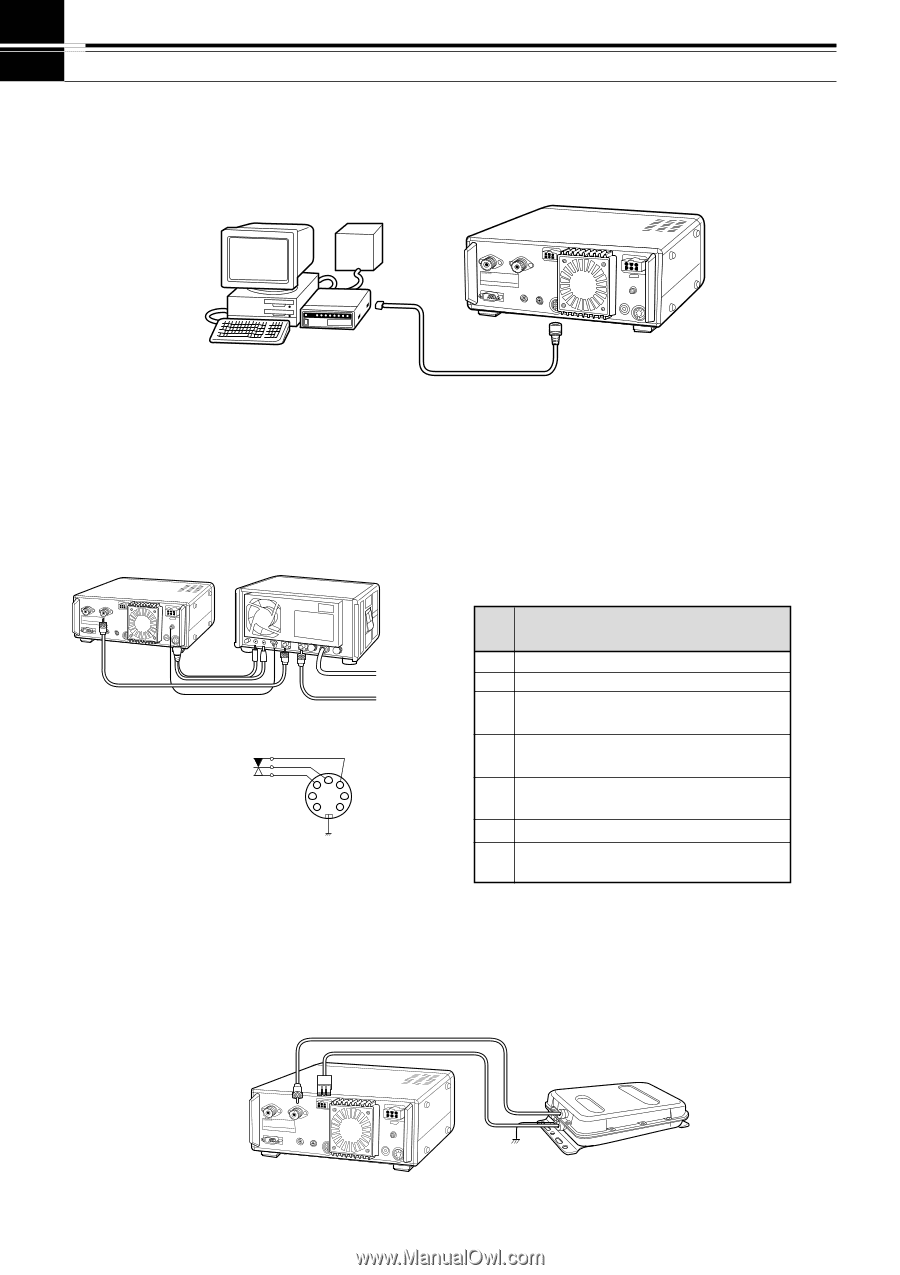
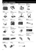
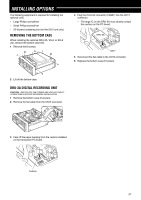
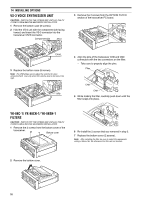
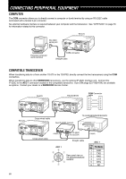
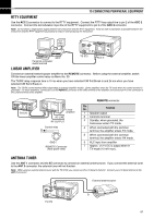
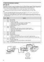
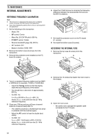
15 CONNECTING PERIPHERAL EQUIPMENT RTTY EQUIPMENT Use the ACC 2 connector to connect to the RTTY equipment. Connect the RTTY key output line to pin 2 of the ACC 2 connector. Connect the demodulation input line of the RTTY equipment to pin 3 of the ACC 2 connector. Note: Do not share a single power supply between the transceiver and the RTTY equipment. Keep as wide a separation as possible between the transceiver and the RTTY equipment as practical to reduce noise-pickup by the transceiver. MCP power supply MCP Personal computer/ dumb terminal TS-570 ACC 2 LINEAR AMPLIFIER Connect an external transmit power amplifier to the REMOTE connector. Before using the external amplifier, switch ON the linear amplifier control relay via Menu No. 39. The TX/RX relay response time is 10 ms when you have selected CW Full Break-in and 25 ms when you have selected CW Semi Break-in. Note: The TX/RX control method differs depending on external amplifier models. Some amplifiers enter the TX mode when the control terminal is grounded. For those amplifiers, connect pin 2 of the REMOTE connector to the GND terminal of the amplifier and connect pin 4 of the connector to the control terminal of the amplifier. TS-570 Linear amplifier AC LINE RF OUTPUT Control relay R T 2 4 5 1 3 6 7 GND REMOTE Connector (Rear panel view) REMOTE connector Pin No. Function 1 Speaker output 2 Common terminal 3 Standby; when grounded, the transceiver enters TX mode. 4 When connected with the common terminal, the amplifier enters TX mode. 5 When connected with the common terminal, the amplifier enters RX mode. 6 ALC input from amplifier 7 Approx. +12 V DC is output when in TX mode (10 mA max.). ANTENNA TUNER Use the ANT 1 connector and the AT connector to connect an external antenna tuner. If you connect the external tuner to the ANT 2 connector, the external tuner will not function. Note: While using an external antenna tuner with the TS-570S, you cannot use the 6 m band to transmit. Connect your 6 m band antenna to the ANT 2 connector. External antenna tuner TS-570 61
-
 1
1 -
2
-
3
-
4
-
5
-
6
-
7
-
8
-
9
-
10
-
11
-
12
-
13
-
14
-
15
-
16
-
17
-
18
-
19
-
20
-
21
-
22
-
23
-
24
-
25
-
26
-
27
-
28
-
29
-
30
-
31
-
32
-
33
-
34
-
35
-
36
-
37
-
38
-
39
-
40
-
41
-
42
-
43
-
44
-
45
-
46
-
47
-
48
-
49
-
50
-
51
-
52
-
53
-
54
-
55
-
56
-
57
-
58
-
59
-
60
-
61
-
 62
62 -
 63
63 -
 64
64 -
 65
65 -
 66
66 -
 67
67 -
 68
68 -
 69
69 -
 70
70 -
 71
71 -
 72
72 -
73
-
74
-
75
-
76
-
77
-
78
-
79
-
80
-
81
-
82
-
83
-
84
-
85
-
86
-
87
-
88
-
89
 |
 |