KitchenAid KDRS807SSS Installation Guide - Page 22
To Convert Standard Surface Burners, To Convert TripleTier, Flame Burner on some models
 |
UPC - 883049027555
View all KitchenAid KDRS807SSS manuals
Add to My Manuals
Save this manual to your list of manuals |
Page 22 highlights
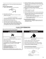
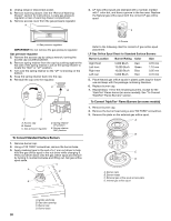
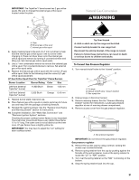
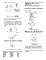
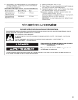
9. Reinstall the cap onto the regulator. A B E D A. Access cap B. Gasket C. Gas pressure regulator C D. Spring retainer NAT position E. Spring retainer LP position To Convert Standard Surface Burners 1. Remove burner cap. 2. Using a T20 TORX® screwdriver, remove the burner base. 3. Apply masking tape to the end of a 7 mm nut driver to help hold the gas orifice spud in the nut driver while changing it. Press nut driver down onto the gas orifice spud and remove by turning it counterclockwise and lifting out. Set gas orifice spud aside. C A D B 5. Place LP gas orifice spuds in plastic parts bag for future use and keep with the package containing literature. 6. Replace burner cap. 7. Repeat steps 1-6 for the remaining burners, except for the TripleTier® Flame burner (on some models). See "To Convert TripleTier® Flame Burners" section. To Convert TripleTier® Flame Burner (on some models) 1. Remove burner cap. 2. Remove the burner head using a size T20 TORX® screwdriver. 3. Remove the plate on the external gas orifice spud. A B C D A. Burner caps B. Burner heads C. External gas orifice spud access plate D. Internal gas orifice spud IMPORTANT: The TripleTier® Flame burner has 2 gas orifice spuds. Be sure to change the external gas orifice spud located under the plate. A A. Igniter electrode B. Gas tube opening C. Burner cap D. Burner base 4. Natural gas orifice spuds are stamped with a number on the side. Replace the LP gas orifice spud with the correct Natural gas orifice spud. XXX A A. Stamped number Refer to the following chart for the correct Natural gas orifice spud placement. Natural Gas Orifice Spud Chart for Standard Surface Burners Burner Location Burner Rating Size Right front Left front Right rear Left rear 6,000 Btu/h 14,000 Btu/h 12,500 Btu/h 6,000 Btu/h 1.10 mm 1.70 mm 1.61 mm 1.10 mm B C A. Plate B. External gas orifice spud C. Internal gas orifice spud 4. Apply masking tape to the end of a 7 mm nut driver to help hold the internal gas orifice spud in the nut driver while changing it. Press nut driver down onto the internal gas orifice spud and remove by turning it counterclockwise and lifting out. Set internal gas orifice spud aside. 5. Use a 7 mm combination wrench to remove the external orifice spud. Turn counterclockwise remove. Set external gas orifice spud aside. 22
-
 1
1 -
2
-
3
-
4
-
5
-
6
-
7
-
8
-
9
-
10
-
11
-
12
-
13
-
14
-
15
-
16
-
 17
17 -
 18
18 -
 19
19 -
 20
20 -
 21
21 -
 22
22 -
 23
23 -
 24
24 -
 25
25 -
 26
26 -
 27
27 -
28
-
29
-
30
-
31
-
32
-
33
-
34
-
35
-
36
-
37
-
38
-
39
-
40
 |
 |
