KitchenAid KHHS179LBL Installation Instructions
KitchenAid KHHS179LBL - 1.7 cu. Ft. Microwave Oven Manual
 |
View all KitchenAid KHHS179LBL manuals
Add to My Manuals
Save this manual to your list of manuals |
KitchenAid KHHS179LBL manual content summary:
- KitchenAid KHHS179LBL | Installation Instructions - Page 1
de instalación. Table of Contents / Índice MICROWAVE OVEN SAFETY 2 VENTING DESIGN SPECIFICATIONS 2 INSTALLATION REQUIREMENTS 3 Tools and Parts 3 Location Requirements 4 Product Dimensions 4 Electrical Requirements 5 INSTALLATION INSTRUCTIONS 5 Remove Mounting Plate 5 Rotate Air Deflector - KitchenAid KHHS179LBL | Installation Instructions - Page 2
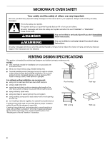
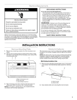
MICROWAVE OVEN SAFETY Your safety and the safety of others are very important. We have provided many important safety messages in this manual and on chance of injury, and tell you what can happen if the instructions are not followed. VENTING DESIGN SPECIFICATIONS This section is intended for - KitchenAid KHHS179LBL | Installation Instructions - Page 3
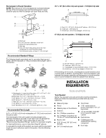
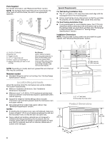
minimum 3" (7.6 cm) clearance must exist between the top of the microwave oven and the rectangular to round transition piece so that the damper can required tools and parts before starting installation. Read and follow the instructions provided with any tools listed here. ■ Measuring tape ■ Stud - KitchenAid KHHS179LBL | Installation Instructions - Page 4
of microwave oven) Aluminum grease filters Charcoal filters (Depending on model, charcoal filters may not be included. See Use and Care Guide.) within cabinet opening. ■ Support for weight of 150 lbs (68 kg), which includes microwave oven and items placed inside the microwave oven and upper cabinet - KitchenAid KHHS179LBL | Installation Instructions - Page 5
or circuit breaker is recommended.) It is recommended that a separate circuit serving only this appliance be provided. GROUNDING INSTRUCTIONS ■ For all cord connected appliances: The microwave oven must be grounded. In the event of an electrical short circuit, grounding reduces the risk of electric - KitchenAid KHHS179LBL | Installation Instructions - Page 6
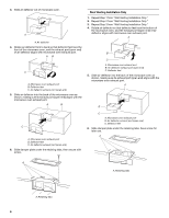
air deflector front to back so that deflector feet face the front of the microwave oven, and the exhaust port (open end) of air deflector aligns with microwave oven exhaust port. A B C A. Microwave oven exhaust port B. Deflector feet C. Air deflector exhaust port (open end) 5. Slide air deflector - KitchenAid KHHS179LBL | Installation Instructions - Page 7
no wall studs exist within the cabinet opening, do not install the microwave oven. 1. Using a stud finder, locate the edges of the (on mounting plate) B. Cabinet opening vertical centerline C. Wall vent opening (on mounting plate) D. Wall stud centerlines E. Holes for lag screws F. Support tabs 7 - KitchenAid KHHS179LBL | Installation Instructions - Page 8
Mark Rear Wall The microwave oven must be installed on a minimum of 1 wall stud, preferably 2, using a minimum of Upper Cabinet Bottom 4" (10.2 cm) ³⁄₈" (1 cm) A. Centerline 2. With the support tabs facing forward (see illustrations in "Possible Wall Stud Configurations" in "Locate Wall Stud(s)" - KitchenAid KHHS179LBL | Installation Instructions - Page 9
stud as well as at all 4 corners. 1. With the support tabs of the mounting plate facing forward, insert 1/4-20 x 3" the holes in the top of the microwave oven. NOTE: If the upper cabinet has cabinet bottom. The template has trim lines to use as guides. 4. Make sure the 10 26.5 cm) dimension from - KitchenAid KHHS179LBL | Installation Instructions - Page 10
each 1/4-20 x 3" bolt and place inside upper cabinet near the 3/8" (10 mm) holes. 2. Make sure the microwave oven door is closed and taped shut. 3. Using 2 or more people, lift microwave oven and hang it on support tabs at the bottom of mounting plate. NOTE: Do not grip or use the door or door - KitchenAid KHHS179LBL | Installation Instructions - Page 11
bolts longer or shorter than 3" (7.6 cm). Longer or shorter bolts are available at most hardware stores. ■ Overtightening bolts may warp the top of the microwave oven. To avoid warping, wood filler blocks may be added. The blocks must be the same thickness as the space between the upper cabinet - KitchenAid KHHS179LBL | Installation Instructions - Page 12
3 prong outlet. ■ See the Use and Care Guide for troubleshooting information. Installation is now complete. Save Installation Instructions for future use. ASSISTANCE Call your authorized dealer or service center. When you call, you will need the microwave oven model number and serial number. Both - KitchenAid KHHS179LBL | Installation Instructions - Page 13
LA COMBINACIÓN MICROONDAS CAMPANA Su seguridad y la seguridad de los demás es muy importante. Hemos incluido muchos mensajes importantes de seguridad en este manual y en su electrodoméstico. Lea y obedezca siempre todos los mensajes de seguridad. Este es el símbolo de advertencia de seguridad. Este - KitchenAid KHHS179LBL | Installation Instructions - Page 14
Tubo de ajuste rectangular a redondo NOTA: Debe haber un espacio mínimo de 3" (7,6 cm) entre la parte superior del horno de microondas y el tubo de ajuste rectangular a redondo para poder abrir la compuerta libre y completamente. A B C D E 3" (7,6 cm) F A. Cubierta del techo B. Ducto de - KitchenAid KHHS179LBL | Installation Instructions - Page 15
del horno de microondas) Filtros para grasa de aluminio Filtros de carbón (Según el modelo, tal vez no se incluyan filtros de carbón. Vea el Manual de Uso y Cuidado.) NOTA: Según el modelo, el filtro de aluminio para grasa y el filtro de carbón pueden combinarse. 15 - KitchenAid KHHS179LBL | Installation Instructions - Page 16
Dimensiones de instalación NOTA: El contacto de pared de conexión a tierra de 3 terminales debe estar dentro del gabinete superior. Vea la sección "Requisitos eléctricos". A B Requisitos eléctricos ADVERTENCIA 30" (76,2 cm) min. 66" (167,6 cm) min. 12" (30,5 cm) min. 14" (35,6 cm) máx. Peligro - KitchenAid KHHS179LBL | Installation Instructions - Page 17
INSTRUCCIONES DE INSTALACIÓN Retire la placa de montaje 1. Saque el contenido restante de la cavidad del horno de microondas. 2. Para sacar la placa de montaje, pele las bandas de la cinta que la sujetan a la parte posterior del horno de microondas y deje la placa de montaje a un lado. A B C 2. - KitchenAid KHHS179LBL | Installation Instructions - Page 18
5. Deslice el desviador de aire dentro de la parte posterior del horno de microondas, como se muestra, cerciorándose de que la lumbrera de escape (extremo abierto) esté alineada con la lumbrera de escape del horno de microondas. A B 4. Rote el desviador de aire de manera que las patas del - KitchenAid KHHS179LBL | Installation Instructions - Page 19
Ubique el(los) pie(s) derecho(s) de pared NOTA: Si no hay pies derechos de pared dentro de la abertura del gabinete, no instale el horno de microondas. 1. Ubique los extremos del(de los) pie(s) derecho(s) de pared dentro de la abertura con un detector de pies derechos. Vea las ilustraciones en " - KitchenAid KHHS179LBL | Installation Instructions - Page 20
Marque la pared posterior El horno de microondas deberá instalarse como mínimo sobre 1 pie derecho de pared, preferentemente 2, usando un mínimo de 1 tirafondo, preferentemente 2 o más. 1. Con la cinta de medir, ubique y marque claramente la línea central vertical de la abertura. A Solamente para - KitchenAid KHHS179LBL | Installation Instructions - Page 21
Instalación para pies derechos de pared en los cuatro orificios de esquina (figura 4) 1. Taladre orificios de 3/16" (5 mm) en los pies derechos de pared en los 4 orificios de esquina que se marcaron en el paso 3 de "Marcar la pared posterior". Ajuste la placa de montaje a la pared NOTA: Asegure la - KitchenAid KHHS179LBL | Installation Instructions - Page 22
Pies derechos de pared en los cuatro orificios de esquina (figura 4) 1. Posicione la placa de montaje en la pared, asegurándose de que la parte superior de la placa de montaje esté alineada con el borde frontal del gabinete superior. 2. Inserte los tirafondos en los 4 orificios de esquina. 3. - KitchenAid KHHS179LBL | Installation Instructions - Page 23
3. Con la ayuda de 2 o más personas, levante el horno de microondas y cuélguelo de las lengüetas de soporte en la parte inferior de la placa de montaje. NOTA: No tome o use la puerta o la manija de la puerta durante la instalación. A B NOTAS: ■ Algunos gabinetes superiores pueden necesitar pernos - KitchenAid KHHS179LBL | Installation Instructions - Page 24
o visite nuestro sitio web. Refacciones Si necesita reemplazar alguna pieza de ferretería de la instalación, llámenos al número gratis que aparece en el Manual de uso y cuidado y tome como referencia el número de pieza apropiado que se enlista aquí. Ensamblaje de la compuerta de tiro Pieza número
-
 1
1 -
 2
2 -
 3
3 -
 4
4 -
 5
5 -
 6
6 -
 7
7 -
8
-
9
-
10
-
11
-
12
-
13
-
14
-
15
-
16
-
17
-
18
-
19
-
20
-
21
-
22
-
23
-
24
 |
 |
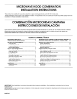
MICROWAVE HOOD COMBINATION
INSTALLATION INSTRUCTIONS
COMBINACIÓN MICROONDAS CAMPANA
INSTRUCCIONES DE INSTALACIÓN
This product is suitable for use above electric or gas cooking products up to 36" (91.4 cm) wide.
These installation instructions cover different models. The appearance of your particular model may differ slightly from the
illustration in these installation instructions.
Este producto puede usarse encima de productos para cocción eléctricos o a gas de 36" (91,4 cm) de ancho o menor.
Estas instrucciones de instalación cubren diferentes modelos. La apariecia de su modelo en particular puede ser
ligeramente diferente de la ilustración en estas instrucciones de instalación.
Table of Contents / Índice
MICROWAVE OVEN SAFETY
...................................................
2
VENTING DESIGN SPECIFICATIONS
.....................................
2
INSTALLATION REQUIREMENTS
...........................................
3
Tools and Parts
.......................................................................
3
Location Requirements
..........................................................
4
Product Dimensions
...............................................................
4
Electrical Requirements
..........................................................
5
INSTALLATION INSTRUCTIONS
.............................................
5
Remove Mounting Plate
.........................................................
5
Rotate Air Deflector
................................................................
5
Locate Wall Stud(s)
.................................................................
7
Mark Rear Wall
.......................................................................
8
Drill Holes in Rear Wall
...........................................................
8
Attach Mounting Plate to Wall
................................................
9
Prepare Upper Cabinet
...........................................................
9
Install Damper Assembly
......................................................
10
Install the Microwave Oven
..................................................
10
Complete Installation
............................................................
12
ASSISTANCE
...........................................................................
12
Replacement Parts
...............................................................
12
Accessories
...........................................................................
12
SEGURIDAD DE LA COMBINACIÓN MICROONDAS CAMPANA ...13
ESPECIFICACIONES PARA EL DISEÑO DE LA VENTILACIÓN
......
13
REQUISITOS DE INSTALACIÓN
.........................................................
15
Piezas y herramientas
........................................................................
15
Requisitos de ubicación
.....................................................................
15
Deminsiones del producto
.................................................................
16
Requisitos eléctricos
..........................................................................
16
INSTRUCCIONES DE INSTALACIÓN
.................................................
17
Retire la placa de montaje
.................................................................
17
Rote el desviador de aire
...................................................................
17
Ubique el(los) pie(s) derecho(s) de pared
..........................................
19
Marque la pared posterior
.................................................................
20
Taladrar orificios en la pared posterior
..............................................
20
Ajuste la placa de montaje a la pared
...............................................
21
Preparación del gabinete superior
.....................................................
22
Instale el ensamblaje de la compuerta de tiro
...................................
22
Instalación del horno de microondas
................................................
22
Complete la instalación
......................................................................
24
ASISTENCIA
..........................................................................................
24
Refacciones
.......................................................................................
24
Accesorios
..........................................................................................
24
IMPORTANT:
Read Installation Instructions thoroughly before beginning installation. Save Installation Instructions for local house
inspector’s use.
IMPORTANTE:
Lea las instrucciones de instalación a fondo antes de comenzar la instalación. Guarde las instrucciones para el uso del
inspector local de la casa.
8205139