KitchenAid KOCE507EBS Installation Instructions
KitchenAid KOCE507EBS Manual
 |
View all KitchenAid KOCE507EBS manuals
Add to My Manuals
Save this manual to your list of manuals |
KitchenAid KOCE507EBS manual content summary:
- KitchenAid KOCE507EBS | Installation Instructions - Page 1
9 Outils et pièces 9 Exigences d'emplacement de l'ensemble four à micro-ondes et four conventionnel encastrés 10 Spécifications électriques 11 INSTRUCTIONS D'INSTALLATION 12 Préparation de l'ensemble four à micro-ondes et four conventionnel encastrés 12 Dépose de la/des porte(s) du four 12 - KitchenAid KOCE507EBS | Installation Instructions - Page 2
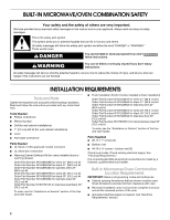
provided many important safety messages in this manual and on your appliance. Always read instructions. WARNING You can be killed or seriously injured if you don't follow instructions. Service" section of the Use and Care Guide. ■ Flush Installation Kit (for Combo installed at flush installation) - KitchenAid KOCE507EBS | Installation Instructions - Page 3
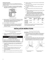
supply junction box should be located 3" (7.6 cm) maximum below the support surface when the oven is installed in a wall cabinet. A 1" (2.5 cm) minimum diameter hole should have been drilled in the left rear corner of the support surface to pass the appliance cable through to the junction box - KitchenAid KOCE507EBS | Installation Instructions - Page 4
■ Do not cut the conduit. The length of conduit provided is for serviceability of the oven. ■ A UL listed or CSA approved conduit connector must be information purposes only: The units are rated in watts. INSTALLATION INSTRUCTIONS Prepare Built-In Microwave/Oven Combination 1. Decide on the final - KitchenAid KOCE507EBS | Installation Instructions - Page 5
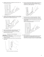
oven door resting on its handle. 7. To continue with the oven installation, go to the "Make Electrical Connection" section. Replace Oven Door(s) IMPORTANT hinge locks. 6. Close the oven door. 7. When the hinges are properly installed and the door closed, there should be an even gap between the door - KitchenAid KOCE507EBS | Installation Instructions - Page 6
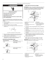
power before servicing. Use 8 gauge solid copper wire. Electrically ground oven. Failure to follow these instructions can result bare) ground wire (in the junction box) using a UL listed wire connector. 6. Install junction box cover. 3-Wire Cable from Home Power Supply - U.S. Only IMPORTANT: Use - KitchenAid KOCE507EBS | Installation Instructions - Page 7
the "Warranty" section of the Use and Care Guide. Install Warming Drawer Deflector Kit (Only for Ovens Installed Above Warming Drawers) On combo microwave/oven models installed above a warming drawer, a warming drawer deflector kit must be installed. See the "Tools and Parts" section for ordering - KitchenAid KOCE507EBS | Installation Instructions - Page 8
E. #8-18 x ³⁄₈" screw Complete Installation 1. Check that all parts are now installed. If there is an extra part, Electrical supply is connected. ■ See "Troubleshooting" section in the Use and Care Guide. 6. When oven has been on Service: Please reference the "Warranty" section of the Use and Care - KitchenAid KOCE507EBS | Installation Instructions - Page 9
immédiatement les instructions. AVERTISSEMENT Risque possible de décès ou de blessure grave si vous ne suivez pas les instructions. Tous les section "Assistance ou service" du Guide d'utilisation et d'entretien. ■ Ensemble d'installation en affleurement (pour four combiné installé en affleurement) - KitchenAid KOCE507EBS | Installation Instructions - Page 10
la section "Spécifications électriques". ■ Le boîtier de raccordement doit être situé au maximum à 3" (7,6 cm) au-dessous de la surface de support lorsque le four est installé dans un placard mural. Un trou de diamètre 1" (2,5 cm) ou plus doit avoir été percé dans l'angle arrière gauche ou droit de - KitchenAid KOCE507EBS | Installation Instructions - Page 11
CSA International 8501 East Pleasant Valley Road Cleveland, OH 44131-5575 Raccordement électrique Pour installer le four correctement, il faut établir le type de raccords électriques que l'on utilisera et suivre les instructions indiquées ici. ■ Le four doit être alimenté par une source d'électricit - KitchenAid KOCE507EBS | Installation Instructions - Page 12
câblage existant pour éviter de le percer ou de l'endommager lors de l'installation. AVERTISSEMENT Risque du poids excessif Utiliser deux ou plus de personnes pour déplacer et installer le four. Le non-respect de cette instruction peut causer une blessure au dos ou d'autre blessure. 2. Pour éviter - KitchenAid KOCE507EBS | Installation Instructions - Page 13
calibre 8. Relier le four à la terre. Le non-respect de ces instructions peut causer un décès, un incendie ou un choc électrique. Le câ . 3. Le cas échéant, enlever le couvercle du boîtier de connexion. 4. Installer un connecteur de conduit (homologation UL ou CSA) sur le boîtier de connexion. A - KitchenAid KOCE507EBS | Installation Instructions - Page 14
États-Unis lorsque les codes locaux ne permettent pas la mise à la terre par l'intermédiaire du conducteur neutre, en cas de nouvelle installation avec alimentation par un circuit secondaire (1996 NEC), dans les résidences mobiles et les véhicules récréatifs, dans les nouvelles constructions, et au - KitchenAid KOCE507EBS | Installation Instructions - Page 15
affichage. 11. Si le tableau d'affichage ne s'allume pas, consulter la section "Garantie" du Guide d'utilisation et d'entretien. Installation de l'ensemble de déflecteur pour tiroir-réchaud (uniquement pour les fours installés au-dessus d'un tiroir-réchaud) Sur les modèles de four à micro-ondes/four - KitchenAid KOCE507EBS | Installation Instructions - Page 16
Avec une vis n° 8-18 x ³⁄₈" (E) pour chaque côté du support de l'évent (B), fixer solidement l'évent au four. A B E 18 x ³⁄₈" Achever l'installation 1. Vérifier que toutes les pièces sont maintenant installées. S'il reste une ou service : Consulter la section "Garantie" du Guide d'utilisation
-
 1
1 -
 2
2 -
 3
3 -
 4
4 -
 5
5 -
 6
6 -
 7
7 -
8
-
9
-
10
-
11
-
12
-
13
-
14
-
15
-
16
 |
 |

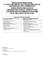
INSTALLATION INSTRUCTIONS
27" (68.6 CM) AND 30" (76.2 CM) ELECTRIC BUILT-IN
MICROWAVE/OVEN COMBINATION
INSTRUCTIONS D'INSTALLATION
ENSEMBLE FOUR À MICRO-ONDES ET FOUR
CONVENTIONNEL ÉLECTRIQUES ET ENCASTRÉS
DE 27" (68,6 CM) ET 30" (76,2 CM)
W10725683B
Table of Contents/Table des matières
BUILT-IN MICROWAVE/OVEN COMBINATION SAFETY
...........
2
INSTALLATION REQUIREMENTS
................................................
2
Tools and Parts
............................................................................
2
Built-In Microwave/Oven Combination
Location Requirements
................................................................
2
Electrical Requirements
...............................................................
3
INSTALLATION INSTRUCTIONS
..................................................
4
Prepare Built-In Microwave/Oven Combination
..........................
4
Remove Oven Door(s)
..................................................................
4
Replace Oven Door(s)
..................................................................
5
Make Electrical Connection
.........................................................
6
Install Oven
...................................................................................
7
Install Warming Drawer Deflector Kit (Only for Ovens
Installed Above Warming Drawers)
..............................................
7
Complete Installation
...................................................................
8
SÉCURITÉ DU FOUR À MICRO-ONDES ET DU FOUR
CONVENTIONNEL COMBINÉS ET ENCASTRÉS
........................
9
EXIGENCES D'INSTALLATION
.....................................................
9
Outils et pièces
.............................................................................
9
Exigences d'emplacement de l'ensemble four
à micro-ondes et four conventionnel encastrés
........................
10
Spécifications électriques
..........................................................
11
INSTRUCTIONS D'INSTALLATION
.............................................
12
Préparation de l'ensemble four à micro-ondes et four
conventionnel encastrés
............................................................
12
Dépose de la/des porte(s) du four
.............................................
12
Réinstallation de la/des porte(s) du four
....................................
12
Raccordement électrique
...........................................................
13
Installation du four
......................................................................
14
Installation de l'ensemble de déflecteur pour tiroir-réchaud
(uniquement pour les fours installés au-dessus d'un tiroir-
réchaud)
......................................................................................
15
Achever l'installation
..................................................................
16
IMPORTANT:
Save for local electrical inspector's use.
IMPORTANT :
À conserver pour consultation par l'inspecteur local des installations électriques.