KitchenAid KUID508HBL Installation Instructions - Page 6
Drain Pump Installation
 |
View all KitchenAid KUID508HBL manuals
Add to My Manuals
Save this manual to your list of manuals |
Page 6 highlights
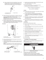
2. Unplug ice maker or disconnect power. 3. Turn off water supply. Wait 5 to 10 minutes for the ice to fall into the storage bin. Remove all ice from bin. 4. Unscrew the drain cap from the bottom of the water pan located inside the storage bin. Allow water to drain completely. Replace drain cap. See "Drain Cap" illustration. Drain Cap 3. Remove the old drain tube and clamp attached to the ice maker bin. NOTE: Discard old drain tube and clamp. 4. Install new drain tube (5/8" I.D. x 5¹⁄8") from ice maker bin to drain pump reservoir inlet using new adjustable clamps. See "Drain Tube" illustration. NOTES: ■ Do not kink. ■ Trim tube length if required. Drain Tube A A. Drain cap 5. If ice maker is built into cabinets, pull ice maker out of the opening. 6. Disconnect water supply line. See "Water Supply Line" illustration. Water Supply Line A B B C D C E A. 1/4" (6.35 mm) copper tubing B. Cable clamp C. 1/4" compression nut D. Ferrule (sleeve) E. Ice maker connection Drain Pump Installation NOTE: Do not kink, smash or damage tubes or wires during installation. 1. Unplug ice maker or disconnect power. 2. Remove rear panel. See "Rear Panel" illustration for 5 screw locations. Pull rear panel away from the drain tube and discard. Rear Panel A A B C D A. 7/8" adjustable hose clamp C. 7/8" adjustable hose clamp B. Drain tube (ice bin to drain pump) D. Drain pump reservoir inlet 5. Install vent tube (5/16" I.D. x 32" [81 cm]) to drain pump reservoir vent. Use one of the supplied 5/8" small adjustable clamp. See "Parts Locations" illustration. NOTE: Do not install household drain tube at this time. Parts Locations A B D E C G F A. Vent tube B. 5/8" hose clamp C. Drain pump discharge tube D. Drain pump E. Ice maker unit power cord F. #8-32 x 3/8" pump mounting screws G. Drain pump power cord, clamp and screw 6. Remove power cord clamp and ground screw attached to ice maker power cord, which is mounted to the unit base. See "Parts Locations" illustration. NOTE: Clamp and screw will be reused. A A. Screw locations 6
-
 1
1 -
 2
2 -
 3
3 -
 4
4 -
 5
5 -
 6
6 -
 7
7 -
 8
8 -
 9
9 -
 10
10 -
 11
11 -
 12
12 -
13
-
14
-
15
-
16
-
17
-
18
-
19
-
20
-
21
-
22
-
23
-
24
-
25
-
26
-
27
-
28
-
29
-
30
-
31
-
32
-
33
-
34
-
35
-
36
 |
 |
