Kyocera C8100DN Technical Reference - Page 113
M5/M6/M7/M8-Host buffer size, R! FRPO M3, 1; EXIT
 |
View all Kyocera C8100DN manuals
Add to My Manuals
Save this manual to your list of manuals |
Page 113 highlights
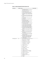
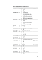
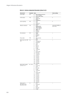
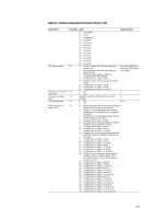
e M5/M6/M7/M8-Host buffer size The printing system utilizes each one buffer for its interfaces. This enables simultaneous receiving of data from the different host computers. The FRPO M5, M6, M7, and M8 parameters determine the ratio among the sizes allocated to these buffers. Parameters M6 and M7 are provided for option interfaces. For example, to allocate the buffers with size ratio of 5:1, use the following format: !R! FRPO M3, 1; FRPO M5, 5; FRPO M6, 1; EXIT; f Ignored in some emulation modes. g Models of low-end category only. h A3/ledger models only. 6-13
-
 1
1 -
2
-
3
-
4
-
5
-
6
-
7
-
8
-
9
-
10
-
11
-
12
-
13
-
14
-
15
-
16
-
17
-
18
-
19
-
20
-
21
-
22
-
23
-
24
-
25
-
26
-
27
-
28
-
29
-
30
-
31
-
32
-
33
-
34
-
35
-
36
-
37
-
38
-
39
-
40
-
41
-
42
-
43
-
44
-
45
-
46
-
47
-
48
-
49
-
50
-
51
-
52
-
53
-
54
-
55
-
56
-
57
-
58
-
59
-
60
-
61
-
62
-
63
-
64
-
65
-
66
-
67
-
68
-
69
-
70
-
71
-
72
-
73
-
74
-
75
-
76
-
77
-
78
-
79
-
80
-
81
-
82
-
83
-
84
-
85
-
86
-
87
-
88
-
89
-
90
-
91
-
92
-
93
-
94
-
95
-
96
-
97
-
98
-
99
-
100
-
101
-
102
-
103
-
104
-
105
-
106
-
107
-
 108
108 -
 109
109 -
 110
110 -
 111
111 -
 112
112 -
 113
113 -
 114
114 -
 115
115 -
 116
116 -
 117
117 -
 118
118 -
119
-
120
-
121
-
122
-
123
-
124
-
125
-
126
-
127
-
128
-
129
-
130
-
131
-
132
-
133
-
134
-
135
-
136
-
137
-
138
-
139
-
140
-
141
-
142
-
143
-
144
-
145
-
146
-
147
-
148
-
149
-
150
-
151
-
152
-
153
-
154
-
155
-
156
-
157
-
158
-
159
-
160
-
161
-
162
-
163
-
164
-
165
-
166
-
167
-
168
-
169
-
170
-
171
-
172
-
173
-
174
-
175
-
176
-
177
-
178
-
179
-
180
-
181
-
182
-
183
-
184
-
185
-
186
-
187
-
188
-
189
-
190
-
191
-
192
-
193
-
194
-
195
-
196
-
197
-
198
-
199
-
200
-
201
-
202
-
203
-
204
-
205
-
206
-
207
-
208
-
209
-
210
-
211
-
212
-
213
-
214
-
215
-
216
-
217
-
218
-
219
-
220
-
221
-
222
-
223
-
224
-
225
-
226
-
227
-
228
-
229
-
230
-
231
-
232
-
233
-
234
-
235
-
236
-
237
-
238
-
239
-
240
-
241
-
242
-
243
-
244
-
245
-
246
-
247
-
248
-
249
-
250
-
251
-
252
-
253
-
254
-
255
-
256
-
257
-
258
-
259
-
260
-
261
-
262
 |
 |

6-13
e
M5/M6/M7/M8—Host buffer size
The printing system utilizes each one buffer for its interfaces. This enables simultaneous receiving
of data from the different host computers. The FRPO M5, M6, M7, and M8 parameters determine
the ratio among the sizes allocated to these buffers. Parameters M6 and M7 are provided for option
interfaces.
For example, to allocate the buffers with size ratio of 5:1, use the following format:
!R! FRPO M3, 1; FRPO M5, 5; FRPO M6, 1; EXIT;
f
Ignored in some emulation modes.
g
Models of low-end category only.
h
A3/ledger models only.