Kyocera TASKalfa 181 PRESCRIBE Commands Technical Reference Manual - Rev. 4.7 - Page 209
KC-GL Environment Options, Parameter Formats
 |
View all Kyocera TASKalfa 181 manuals
Add to My Manuals
Save this manual to your list of manuals |
Page 209 highlights
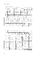
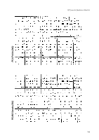
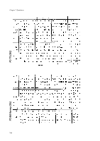
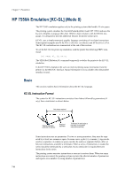
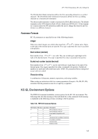
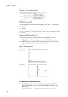
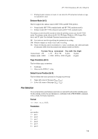
HP 7550A Emulation [KC-GL] (Mode 8) The SM (Symbol Mode) instruction defines the first succeeding character as a symbol character. The DT (Define label Terminator) instruction defines the first succeeding character as a character plot terminator. The character plot terminator is used to terminate the LB (LaBel) instruction. The default terminator is the ETX character (End of Text), which uses ASCII code 3. If this terminator is inconvenient, the DT instruction enables the user to change the character plot terminator to a different character. Parameter Formats KC-GL parameters are specified in one of the following formats: Integer When not scaled, integers are valid in the range from -223 to 223-1 plotter units. Digits to the right of the decimal point are ignored. If no sign is specified, the value is assumed to be positive. Real number (decimal) Real numbers from -223 to 223-1 are valid. They can include up to eight digits to the right of the decimal point. If no sign is specified, the value is assumed to be positive. Scaled real number (scaled decimal) Real numbers from -223 to 223-1 can be used with up to eight digits to the right of the decimal point. If no sign is specified, the value is assumed to be positive. Scaled real numbers are used only with scaled user units. All KC-GL parameters that are interpreted as user units are scaled. Character string A combination of characters, numeric expressions, and string variables. When coding an instruction with two or more parameters (Examples: PA, PR, PU, PD) remember that the parameters must be set apart by a separator. KC-GL Environment Options The FRPO G0 command establishes various options for the KC-GL environment. The following table lists the meanings of the individual bits in the command. Each meaning is explained in the following sections according to the bit position. Table 7.28. FRPO G0 Command Options Bit Position Bit Value Logic Value Description 0 0 0 Plot coordinate mode A 1 1 Plot coordinate mode B 1 0 0 Form feed in response to SP 2 1 SP 2 0 0 Automatic plot coordinate transition 4 1 Fixed plot coordinate 3 0 0 Normal mode 8 1 Enhance mode 7-97
-
 1
1 -
2
-
3
-
4
-
5
-
6
-
7
-
8
-
9
-
10
-
11
-
12
-
13
-
14
-
15
-
16
-
17
-
18
-
19
-
20
-
21
-
22
-
23
-
24
-
25
-
26
-
27
-
28
-
29
-
30
-
31
-
32
-
33
-
34
-
35
-
36
-
37
-
38
-
39
-
40
-
41
-
42
-
43
-
44
-
45
-
46
-
47
-
48
-
49
-
50
-
51
-
52
-
53
-
54
-
55
-
56
-
57
-
58
-
59
-
60
-
61
-
62
-
63
-
64
-
65
-
66
-
67
-
68
-
69
-
70
-
71
-
72
-
73
-
74
-
75
-
76
-
77
-
78
-
79
-
80
-
81
-
82
-
83
-
84
-
85
-
86
-
87
-
88
-
89
-
90
-
91
-
92
-
93
-
94
-
95
-
96
-
97
-
98
-
99
-
100
-
101
-
102
-
103
-
104
-
105
-
106
-
107
-
108
-
109
-
110
-
111
-
112
-
113
-
114
-
115
-
116
-
117
-
118
-
119
-
120
-
121
-
122
-
123
-
124
-
125
-
126
-
127
-
128
-
129
-
130
-
131
-
132
-
133
-
134
-
135
-
136
-
137
-
138
-
139
-
140
-
141
-
142
-
143
-
144
-
145
-
146
-
147
-
148
-
149
-
150
-
151
-
152
-
153
-
154
-
155
-
156
-
157
-
158
-
159
-
160
-
161
-
162
-
163
-
164
-
165
-
166
-
167
-
168
-
169
-
170
-
171
-
172
-
173
-
174
-
175
-
176
-
177
-
178
-
179
-
180
-
181
-
182
-
183
-
184
-
185
-
186
-
187
-
188
-
189
-
190
-
191
-
192
-
193
-
194
-
195
-
196
-
197
-
198
-
199
-
200
-
201
-
202
-
203
-
 204
204 -
 205
205 -
 206
206 -
 207
207 -
 208
208 -
 209
209 -
 210
210 -
 211
211 -
 212
212 -
 213
213 -
 214
214 -
215
-
216
-
217
-
218
-
219
-
220
-
221
-
222
-
223
-
224
-
225
-
226
-
227
-
228
-
229
-
230
-
231
-
232
-
233
-
234
-
235
-
236
-
237
-
238
-
239
-
240
-
241
-
242
-
243
-
244
-
245
-
246
-
247
-
248
-
249
-
250
-
251
-
252
-
253
-
254
-
255
-
256
-
257
-
258
-
259
-
260
 |
 |