Kyocera TASKalfa 520i Fax System (S) C Operation Guide Rev-2 - Page 20
Machine, Part Names and Functions, OPERATION GUIDE - copier
 |
View all Kyocera TASKalfa 520i manuals
Add to My Manuals
Save this manual to your list of manuals |
Page 20 highlights
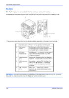
Part Names and Functions Machine This chapter explains the names of parts when the machine is used as a fax machine. For the parts required when functions other than FAX are used, refer to the machine's Operation Guide. 1 5 4 6 42/52 ppm model or the 2 full-color model 3 2 30 ppm model * The operation panel may differ from the above illustration depending on the type of your machine. 1 Operation panel Perform the fax operation with this panel. 2 Main power switch Set this switch to the ON (|) side when performing the fax or copier operation. The touch panel lights to enable operation. 3 MP (Multi Purpose) tray Set the paper in this tray when using a type of paper other than the cassette (e.g., when using special paper). 4 LINE connector Connect the modular cord for the telephone (L1) line to this connector. This connector is Port 1. 5 LINE connector If you install 2 optional FAX Kits (Dual FAX (L2) option), you can use Port 2. Connect the modular cord for the telephone line to this connector. 6 TEL connector When using a commercially available (T1) telephone set, connect the modular cord to this connector. IMPORTANT: You cannot automatically receive a fax when the main power switch is turned off. To receive faxes with the power turned off, press the Power key on the operation panel. 1-4 OPERATION GUIDE
-
 1
1 -
2
-
3
-
4
-
5
-
6
-
7
-
8
-
9
-
10
-
11
-
12
-
13
-
14
-
 15
15 -
 16
16 -
 17
17 -
 18
18 -
 19
19 -
 20
20 -
 21
21 -
 22
22 -
 23
23 -
 24
24 -
 25
25 -
26
-
27
-
28
-
29
-
30
-
31
-
32
-
33
-
34
-
35
-
36
-
37
-
38
-
39
-
40
-
41
-
42
-
43
-
44
-
45
-
46
-
47
-
48
-
49
-
50
-
51
-
52
-
53
-
54
-
55
-
56
-
57
-
58
-
59
-
60
-
61
-
62
-
63
-
64
-
65
-
66
-
67
-
68
-
69
-
70
-
71
-
72
-
73
-
74
-
75
-
76
-
77
-
78
-
79
-
80
-
81
-
82
-
83
-
84
-
85
-
86
-
87
-
88
-
89
-
90
-
91
-
92
-
93
-
94
-
95
-
96
-
97
-
98
-
99
-
100
-
101
-
102
-
103
-
104
-
105
-
106
-
107
-
108
-
109
-
110
-
111
-
112
-
113
-
114
-
115
-
116
-
117
-
118
-
119
-
120
-
121
-
122
-
123
-
124
-
125
-
126
-
127
-
128
-
129
-
130
-
131
-
132
-
133
-
134
-
135
-
136
-
137
-
138
-
139
-
140
-
141
-
142
-
143
-
144
-
145
-
146
-
147
-
148
-
149
-
150
-
151
-
152
-
153
-
154
-
155
-
156
-
157
-
158
-
159
-
160
-
161
-
162
-
163
-
164
-
165
-
166
-
167
-
168
-
169
-
170
-
171
-
172
-
173
-
174
-
175
-
176
-
177
-
178
-
179
-
180
-
181
-
182
-
183
-
184
-
185
-
186
-
187
-
188
-
189
-
190
-
191
-
192
-
193
-
194
-
195
-
196
-
197
-
198
-
199
-
200
-
201
-
202
-
203
-
204
-
205
-
206
-
207
-
208
-
209
-
210
-
211
-
212
-
213
-
214
-
215
-
216
-
217
-
218
-
219
-
220
-
221
-
222
-
223
-
224
 |
 |
