LG 580.72124 200 Owners Manual - Page 7
About
 |
View all LG 580.72124 200 manuals
Add to My Manuals
Save this manual to your list of manuals |
-
 1
1 -
 2
2 -
 3
3 -
 4
4 -
 5
5 -
 6
6 -
 7
7 -
 8
8 -
 9
9 -
 10
10 -
 11
11 -
 12
12 -
13
-
14
-
15
-
16
-
17
-
18
-
19
-
20
-
21
-
22
-
23
-
24
-
25
-
26
-
27
-
28
-
29
-
30
-
31
-
32
-
33
-
34
-
35
-
36
 |
 |

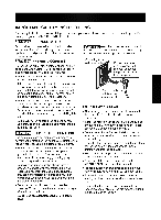
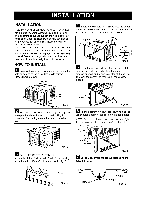
Select
the
position
that
will
place
the
sill
supports
near
the
outermost
point
on
sill
(FIG.
10).
Attach
the
sill
supports
to
the
cabinet
track
hole
closest
to
the
selected
position
using
screw
(ITEM
E).
Place
the
sill
supports
with
the
cabinet
on
the
window
sill's
selected
position
(FIG.
10).
The
cabinet
should
be
installed
with
a
very
slight
tilt
(about
1/4")
downward
to
the outside
(FIG.
11).
Adjust
the
bolts
and
the
nuts
of
sill
supports
to
level
the
cabinet.
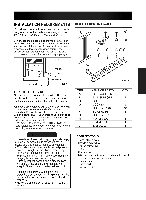
Attach
the
cabinet
to
the
inner
sill
by
driving
the
screws
(ITEM
F)
through
the
front
lower
guide
into
the
window
inner
sill.
(FIG.
12)
Pull
each
side
curtain
fully
to
each
side
of
window
opening.
Attach
each
side
curtain
to
the
window
sash
using
screws
(ITEM
G).
(FIG.
13)
Attach
the
L
bracket
(ITEM
J)
with
screw
(ITEM
G)
(FIG.
14).
DRAINAGE
Be
sure
to
insert
the
drain
pipe
into
base
pan
before
installation.
The
air
conditioner
must
be
installed
with
a
slight
tilt
downward
to
the
outside
for
proper
water
drainage
(FIG.
15).
Slide
the
air
conditioner
into
the
cabinet.
(FIG. 16)
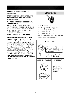
CAUTION:
For
security
purposes,
reinstall
side
screws
you
removed
in
step
1.
Cut
the
foam
seal
(ITEM
H)
to
the
proper
length
and
insert
between
the
upper
window
sash
and
the
lower
window
sash.
(FIG.
17)
The
vent
control
handle
must
be
straightened
before
the
decorative
front
is
attached.
Pull
down
part
to
align
with
part
-7-
ITEM
H
Part
FIG.
17
FIG.
18
Sash
Track
ITEM
F
ITEM
B
Lower
Guide
FIG.
12
ABOUT "
/
14
ITEM
B
Screw
Screw
Power
Cord
FIG.
11
ITEM
G
ITEM
G
ITEM
J
BASE
PAN
REAR
DRAIN
PIPE
BASE
PAN
BOTTOM
FIG.
13
FIG.
15
FIG.
14
INDOOR
OUTDOOR
ABOUT /
14"
Cabinet
ITEM
E
Lower
guide
FIG.
10
FIG.
16
Part