LG ARUN038GS2 Installation Manual - Page 71
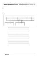
Valve 04, Valve 03, Valve 02, Valve 01, Indoor unit 04, Indoor unit 03, Indoor unit 02, Indoor unit
 |
View all LG ARUN038GS2 manuals
Add to My Manuals
Save this manual to your list of manuals |
Page 71 highlights
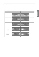
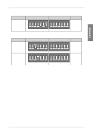
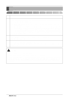
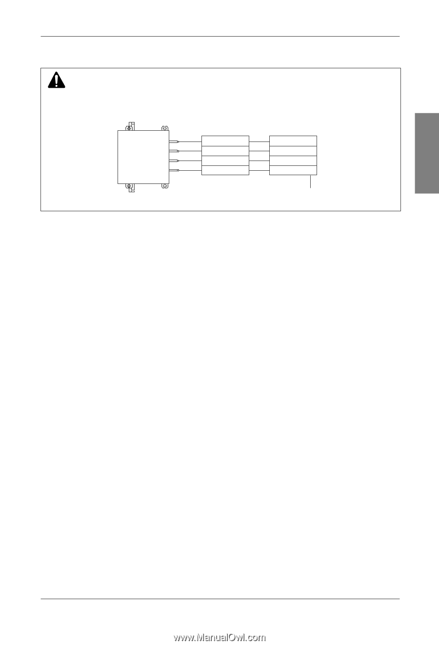
Main PCB WARNING • Valve address and central control address of its corresponding indoor unit should be set identical in manual addressing. EX) HR unit Valve (04) Valve (03) Valve (02) Valve (01) Indoor unit (04) Indoor unit (03) Indoor unit (02) Indoor unit (01) Central control address ENGLISH Installation Manual 71
-
 1
1 -
2
-
3
-
4
-
5
-
6
-
7
-
8
-
9
-
10
-
11
-
12
-
13
-
14
-
15
-
16
-
17
-
18
-
19
-
20
-
21
-
22
-
23
-
24
-
25
-
26
-
27
-
28
-
29
-
30
-
31
-
32
-
33
-
34
-
35
-
36
-
37
-
38
-
39
-
40
-
41
-
42
-
43
-
44
-
45
-
46
-
47
-
48
-
49
-
50
-
51
-
52
-
53
-
54
-
55
-
56
-
57
-
58
-
59
-
60
-
61
-
62
-
63
-
64
-
65
-
 66
66 -
 67
67 -
 68
68 -
 69
69 -
 70
70 -
 71
71 -
 72
72 -
 73
73 -
 74
74 -
 75
75 -
 76
76 -
77
-
78
-
79
-
80
-
81
-
82
-
83
-
84
-
85
-
86
-
87
-
88
-
89
-
90
-
91
-
92
-
93
 |
 |
ENGLISH
Installation Manual
71
Main PCB
WARNING
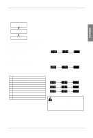
• Valve address and central control address of its corresponding indoor unit should be set identical in manual
addressing.
Valve (04)
EX)
Valve (03)
Valve (02)
Valve (01)
Indoor unit (04)
Indoor unit (03)
Indoor unit (02)
Indoor unit (01)
Central control address
HR unit