LG DLEV833W Owners Manual - Page 15
uirements, And Ma
 |
View all LG DLEV833W manuals
Add to My Manuals
Save this manual to your list of manuals |
Page 15 highlights
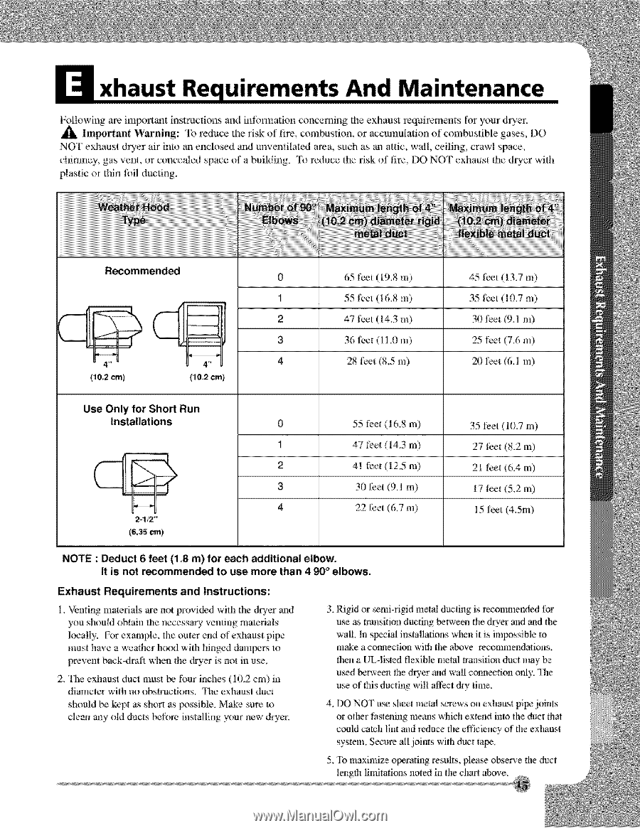
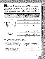
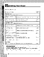
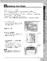
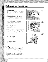
uirements And Ma l-:ollowing are important instructions and infonnation concerning the exhaust requirements tor your dryer. Important Warning:: To reduce the :risk of fire, combustion, or accumulation of combustible gases, DO NOT exhaust dryer air into an enclosed and mwentilated area, such as an attic, wall, ceiling, crawl space, chimney, gas vent, or concealed space of a building. "lb reduce the risk of fire, DO NOT' exhaust the dQcer with plastic or thin foil ducting. 0 65 feet (19.8 m) 45 feet (I3.7 m) 1 55 I)et (16.8 m) 35 feet (10.7 m) 2 47 feet (14.3 m) 30 feet (9.1 m) 3 36 feet (11.0 m) 25 feet (7.6 m) 4 28 feet (8.5 m) 20 t)et (6. I m) Use Only for Short Run Installations {6,35 cm) 0 55 fce_ (i 6.8 m) 35 l?eet (10.7 m) 1 47 fret (14.3 m) 27 feet (18.2m) 2 41 fL'et (12.5 m) 21 l_et (6.4 m) 3 30 feet (9.1 m) 17 feet (5.2 m) 4 22 feet (6.7 m) 15 feet (4.5m) NOTE : Deduct 6 feet (1_8 m)for each additional elbow. It is not recommended to use more than 4 _° elbows. Exhaust Requirements and Instructions: 1. Vendng materials are not provided with the dwcr aud you should obtain the necess_y venting materials locally. For ex:ample, the outer end of exhaust pipe must have a weaher hood with hinged dampe_ m prewent back_drafl when the @er is not in use. 2. The exhaust duct must be four inches (10.2 cm) in diameter with no obslrucfions. The exhaust duct should be kept as shor! as possible. Make sure to clean any old ducts before instNling your new dryer. 3. Rigid or semi-rigid metal ducting is rc,conm_ended tor u_ as transition ducth_g between the dryer and and fl_e wal!. h_ s_ial installations when it is impossible m make a coimecdon with the above recommendations, then a UL-lisled flexible metal transition duct may u_d betwee_ fl_e dryer and wall conneclion only. The u_ of this ducting will affect dry time. 4. DO NO]" u_ sheet metal screws on exhaust pi_ joints or other thstening means which ex_end into the duct that could catch lint and reduce the efficiency of the exlmust system. Secure all joints with duct rope. 5. To maximize operating results, please observe the duct length limitations noted in the chart above.
-
 1
1 -
2
-
3
-
4
-
5
-
6
-
7
-
8
-
9
-
 10
10 -
 11
11 -
 12
12 -
 13
13 -
 14
14 -
 15
15 -
 16
16 -
 17
17 -
 18
18 -
 19
19 -
 20
20 -
21
-
22
-
23
-
24
-
25
-
26
-
27
-
28
-
29
-
30
-
31
-
32
-
33
-
34
-
35
-
36
-
37
-
38
-
39
-
40
-
41
-
42
-
43
-
44
-
45
-
46
-
47
-
48
-
49
-
50
-
51
-
52
-
53
-
54
-
55
-
56
-
57
-
58
-
59
-
60
-
61
-
62
-
63
-
64
-
65
-
66
-
67
-
68
 |
 |