LG DLEX3885W Owners Manual - Page 23
Warh|ng
 |
View all LG DLEX3885W manuals
Add to My Manuals
Save this manual to your list of manuals |
Page 23 highlights
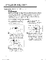
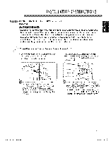
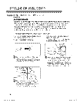
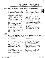
INSTALLATIONINST UCTIONS cONNEcTiNG ELEcTRic DRYERS {cont.) USA ONLY , WARH|NG: • Connect the power cord to the terminal block. Each colored wire should be connected to same color screw. Wire color indicated on manual is connected to the same color screw in block. Failure to follow these instructions may result in a short or overload. • Grounding through the neutral conductor is prohibited for: (1) new branch-circuit installations, (2) mobile homes, (3) recreational vehicles, and (4) areas where local codes prohibit grounding through the neutral conductor. © Three-wire Connection for Electric Dryers: Power Cord • A 3-wire connection is NOT permitted on new construction after January 1, 1996. • A UL-Iisted strain relief is required. Terminal Block UL-Listed Strain Relief • Use a 30 A, 240 V, UL=listed power cord with #10 AWG=minimum copper conductor and closed loop or forked terminals with upturned ends. f _,,_ Hot (Black) (White) (Red) ...... Jr Ground Screw r , L' oi 1, Neutral Grounding wire"-_v___ Remove the terminal block access cover on the upper back of the dryer. Install a UL-Iisted strain relief into the power cord through-hole; then thread a UL-Iisted, 30 A, 240 V, 3-wire, #10 AWG-minirnum copper conductor power cord through the strain relief. Attach the two hot leads of the power cord to the outer terminal block screws. Attach the neutral wire to the center terminal block screw. Connect the external ground (if required by local codes) to the green ground screw. TIGHTEN ALL SCREWS SECURELY. Reinstall the terminal block access cover. MFL62512806 EN 0208.indd 23 25 2010.2.8 2:7:8 PM
-
 1
1 -
2
-
3
-
4
-
5
-
6
-
7
-
8
-
9
-
10
-
11
-
12
-
13
-
14
-
15
-
16
-
17
-
 18
18 -
 19
19 -
 20
20 -
 21
21 -
 22
22 -
 23
23 -
 24
24 -
 25
25 -
 26
26 -
 27
27 -
 28
28 -
29
-
30
-
31
-
32
-
33
-
34
-
35
-
36
-
37
-
38
-
39
-
40
-
41
-
42
-
43
-
44
-
45
-
46
-
47
-
48
-
49
-
50
-
51
-
52
-
53
-
54
-
55
-
56
-
57
-
58
-
59
-
60
-
61
-
62
-
63
-
64
-
65
-
66
-
67
-
68
-
69
-
70
-
71
-
72
-
73
-
74
-
75
-
76
-
77
-
78
-
79
-
80
-
81
-
82
-
83
-
84
-
85
-
86
-
87
-
88
-
89
-
90
-
91
-
92
-
93
-
94
-
95
-
96
-
97
-
98
 |
 |
