LG LMCN185HV Service Manual - Page 4
Piping Diagrams
 |
View all LG LMCN185HV manuals
Add to My Manuals
Save this manual to your list of manuals |
Page 4 highlights
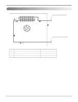
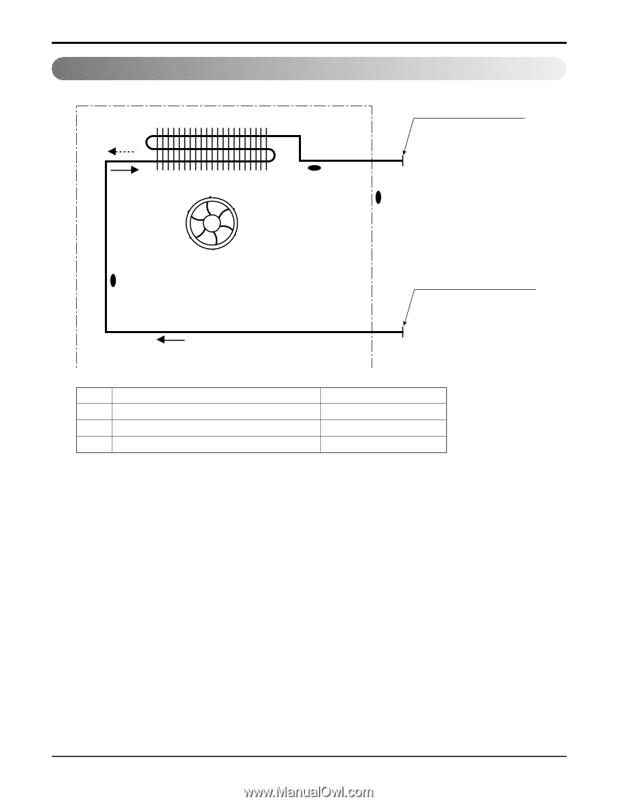
3. Piping Diagrams Heating Heat exchanger Cooling Turbo fan Gas pipe connection port (flare connection) Th3 Th1 Th2 Liquid pipe connection port (flare connection) LOC. Th1 Th2 Th3 Description Thermistor for sunction air temperature Thermistor for evaporator inlet temperature Thermistor for evaporator outlet temperature PCB Connector CN_ROOM CN_PIPE/IN CN_PIPE/OUT Copyright ©2008 LG Electronics. Inc. All right reserved. Only for training and service purposes -4- LGE Internal Use Only
-
 1
1 -
 2
2 -
 3
3 -
 4
4 -
 5
5 -
 6
6 -
 7
7 -
 8
8
 |
 |
- 4 -
Copyright ©2008 LG Electronics. Inc. All right reserved.
Only for training and service purposes
LGE Internal Use Only
3. Piping Diagrams
Heat exchanger
Gas pipe connection por
t
(flare connection)
Liquid pipe connection por
t
(flare connection)
Cooling
Heating
Turbo fan
Th3
Th1
Th2
LOC.
Description
PCB Connector
Th1
Thermistor for sunction air temperature
CN_ROOM
Th2
Thermistor for evaporator inlet temperature
CN_PIPE/IN
Th3
Thermistor for evaporator outlet temperature
CN_PIPE/OUT