LG LRBP1031W User Guide
LG LRBP1031W - 10 Cu. Ft. Cabinet Depth Bottom Freezer Refrigerator Manual
 |
UPC - 048231777223
View all LG LRBP1031W manuals
Add to My Manuals
Save this manual to your list of manuals |
LG LRBP1031W manual content summary:
- LG LRBP1031W | User Guide - Page 1
point. (Figure 1) Replace the filter and any damaged components. Unsolder and pull off the piece remaining inside the service tube and then attach be obtained (pressure gauge can't fall to 1 atmosphere), start the refrigeration unit and find the leakage with the special leak-finder. When the - LG LRBP1031W | User Guide - Page 2
C,_PA_m3_ p,TJC -- E_Rm P/_T 3854JD1026A BK:BLACK BN:BROWN RD:RED BO:BRIGHOTRANGE YL:YB.LOW GN,GREB_ BL:BLUE PR:PURPLE GY:GRAY WH:WHITE SB:SKYBLUE PK:PINK GF_.:GREEN/YELLOW WH_K.'WHITF.._LACK - LG LRBP1031W | User Guide - Page 3
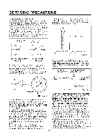
PARTS IDENTIFICATION Freezer Temperature _ Control Removable Glass Shelf(2 or 3) Lam Multi-air Flow Fresh Meat Kee (Optional) Temperature Control Utility Comer (movable) Bottle Holder -2J_ Bottle Door Basket Screw NOTE : This is a basic model. The shape of refrigerator is subject to change. -5- - LG LRBP1031W | User Guide - Page 4
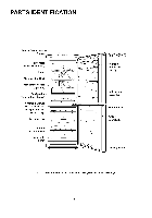
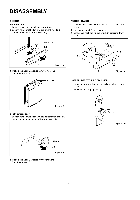
out food and accessories like shelves or trays which are not fixed in the refrigerator. 2) Use Torque Wrench or Spanner to fix or remove the bolt. 3) Don't lay the refrigerator down in working with it, it will cause to get out of order, 4) Be careful not to drop the door in disassembling or - LG LRBP1031W | User Guide - Page 5
only. Lower Hinge 2 DOOR SWITCH 1) Loosen four screws in upper part and disconnect top cover. 2) Disconnect Lead Wire from switch. 3) Figure 7 • Refrigerator Door 1) Loosen hexagonal bolts fixing the center hinge(Hinge,C) to the body to remove the refrigerator door only. Figure 10 e,C Figure 8 - LG LRBP1031W | User Guide - Page 6
the Defrost Control Assy and replace new one. Figure 13 7 HEATER, SHEATH In this refrigerator, Heater, Sheath is used for defrosting heater. During heating, the temperature of heater rises about 300-500°C. Therefore, be careful not to burn while servicing - LG LRBP1031W | User Guide - Page 7
of dust or humidity, deal and repair with care. 3) Note for Usage (4) Note to Keep Compressor. If Compressor gets wet in the rain and rust in don't inflow in the Compressor inside in replacing the Compressor. Dust, humidity, and flux . for pressure balance of Refrigerating Cycle and PTC cooling. - LG LRBP1031W | User Guide - Page 8
of the OLP (1) The OLP is attached to the Hermetic Compressor used for the Refrigerator and Show Case and prevents the Motor Coil from being started in the Compressor. WH:WHITE GN/YL:GREENHELLOW WH/BK;WHITEtBLACK NOTE : 1. This is a basic diagram and specifications vary in different localities - LG LRBP1031W | User Guide - Page 9
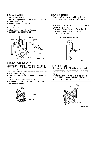
TROUBLESHOOTING (Mechanical Part) 1 COMPRESSOR AND ELECTRIC COMPONENTS SPoouwrecer . Remove the PTC]_ Starter from the Compressor and measure the voltage between Terminal C of Compressor and Terminals 5 or 6 of PTC. (Rating Voltage _+10%)? YES _ OLP disconnected? YES Replace OLR in the - LG LRBP1031W | User Guide - Page 10
_+30% 115V/60Hz : 6.8§ _+30% 240V/50Hz : 33§ _+30% 127, 220V/60Hz : 22§ +_3O% electric t Ccohmecpkonaennotsth. er . 'orost,'a c v or serveral hundreds §. Replace PTC-Starter. Separate the OLP from the _ Compressor and check the resistance value between two terminals of OLP with a Tester. (Figure - LG LRBP1031W | User Guide - Page 11
_ the following components. a. Thermistor b. Starting devices c. OLP d. Compressor coil e. Circuit Parts Cause. _- Poor contacting. Shorted or broken. _, Poor contacting or shorted. Coil shorted. Poor contacting or shorted. Replace each component. Running state of Compressor is poor. ] Check - LG LRBP1031W | User Guide - Page 12
"cold-position". , is foods placed in cooling air outlet? , Check if the control is set to "cold- . • Place foods in high temperature section. (Front Part) • Set the control to "mid-position". • Replace the Components of defrosting circuit. Check Refrigerating Cycle. The cycle is faulty. Repair - LG LRBP1031W | User Guide - Page 13
5 REFRIGERATING CYCLE • Troubleshooting Chart CAUSE STATE OF THE SET STATE OF THE EVAPORATOR PARTIAL LEAKAGE mr> > WHOLE LEAKAGE o PARTIAL CLOG mu £U -< WHOLE CLOG 03 MOISTURE CLOG Freezer room and Refrigerator don't cool normally, Low flowing sound of Refrigerant is heard and frost forms in - LG LRBP1031W | User Guide - Page 14
Refrigerating Cycle NO. ITEMS WELDINg ROD FLUX DRIER ASM VACUUM DRY AND AIR NITROGEN GAS NIPPLE 6 AND COUPLER PiPE 7 CONTENTS AND SPECIFICATIONS REMARKS (1) H 30 • Chemical Ingredients Ag: 30%, Cu in the FLUX. • Keep it in a stainless steel container. (1) Assemble the drier within 30min. - LG LRBP1031W | User Guide - Page 15
& PCB CIRCUIT EXPLANATION This description is made for GR-349, 389SQ. Please refer to overall PCB circuits for other models. 1 FUNCTION EXPOSITION 1) FUNCTION (1) The refrigerator starts from optimum condition when electric power is first on, But the operation condition changes "Mid" "Mid/Max" _"Max - LG LRBP1031W | User Guide - Page 16
7°C after 2 hours' operation of the defrosting heater, it represents a defrosting trouble.(See the TROUBLE REPRESENTING FUNCTION) (4) If DEFROST SENSOR is short or open, defrosting is not performed. 7) ORDERLY OPERATION OF ELECTRIC PARTS To avoid NOISE and DAMAGE, the items containing an electric - LG LRBP1031W | User Guide - Page 17
8) SELF-TEST (1) Function to make service easy in case of occuring a trouble in the product. (2) When occurring a trouble, if the button is pushed, but the function could not operate. (3) If a toruble release during the representation of trouble, a refrigerator performs the normal function(RESET). - LG LRBP1031W | User Guide - Page 18
9) FUNCTION TEST (1) Function to check the testing function of PCB and refrigerator and to find where the trouble. (2) The test switch is on the MAIN PCB of refrigerator. TEST FUNCTION is released and RESET after MAX. 2hours regardless of TEST MODE. (3) If the buttons on TOP COVER is pushed during - LG LRBP1031W | User Guide - Page 19
for supplying electricity to MICOM and IC (5Vdc). The voltage in each part is as follows. PARTS both ends of VA1 both ends of CM1 both ends of CM2 both time. Use a proper form for OSC 1, Because in case that SPECIFICATION is changed, the calculated time in IC1 is changed or IC1 isn't able to - LG LRBP1031W | User Guide - Page 20
OPENING PERCEPTION CHECK CON3 _E *NOTICE: If you would change DOOR S/W-R, must use the componenot of right PART NUMBER, Because there is a similar type DOOR StW-R of NOT MICOM MODEL, it's logic of the (_, (_ of DOOR StW-R is reversed. _MEASURING REFRIGERATDO_R POINT NO.6 OF IC 1 (MICOM) CLOSE - LG LRBP1031W | User Guide - Page 21
(3)BUZZER OPERATION CHECK 14 R55/BUZ R40/INT0 CONDITIONS MEASURI_ POINT _- ICl (No.14 Pin) 5v OV-- DISPLAY FUNCTION BUTTON RING (DING~ DONG~) !O.05si_ 0.2s _!O.lsi_ ls : , i , i _ -- i / ICl (No.13 Pin) J 5V I / 0V-- !_ 2.66khz(DING) ! 2.232khz/DONG_/ ! DOOR OPEN ALARM ( - LG LRBP1031W | User Guide - Page 22
5) TEMP SENSOR CIRCUITS R67 (AN7) CClO_ 223/?[ 7 R65 10 (AN5) R64 (AN4) cc8_ cc71 223 f?[7 CON3 CON101 \\\ T RF3 R19 _ 261KF 2K @ \\\ R16 _,_ "_' \ INPUT CIRCUIT The following circuit is a test switch input circuit for checking the refrigerator. ICl R56 _s TEST S/W Go - 24 - - LG LRBP1031W | User Guide - Page 23
ROOM RESISTANCE VALUES(R1) TEMPERATURE COMPENSATION 180 k_ + 5.0°C 56 k_ +4.0°C 33 k_ +3.0°C 18 k_ +2.0°C 12 k_ +1.0°C 10 k_ O°C 8.2 k_ -1.O°C 5.6 k_) -2.0°C 3.3 k_) _3.0°C 2 k£_ 4.0°C 470 £_ _5.0oc REMARKS COMPENSATE WARMLY J STANDARD COMPENSATE COOLLY • TEMPERATURE - LG LRBP1031W | User Guide - Page 24
circuit is aimed to input the necessary temperature compensation values into the MICOM in order to adjust the freezer temperature which is different in each model. - 26 - - LG LRBP1031W | User Guide - Page 25
DSPO _ L5_ 5 }SP1 VAC 4 }SP2 ./ _CC6 _7 lo2 IR14 5 /o SV,lg2 ya sva0,_ VACATION FREEZER TEMP QUICK FREEZE KEY CONTROL KEY KEY DISPLAY PART j The above circuit is to judge the operation conditions of function key and to light each function indicating LED. It is operated by SCAN - LG LRBP1031W | User Guide - Page 26
MEASUREDTEMPERATURE RESISTANCEOFFREF..ZERSENSORRESISTANCEOFDEFROSTSENSROORO,MTEMPERATURESENSOR _20°C 22.3k_ 77k_ -15°C 16.9kD 60kD -10°C 13.0kD 47.3kD -5°C 10.1kD 38.4kD 0°C 7.8kD 30kD +5°C 6.2kD 24.1kD +10°C 4.9kD 19.5kD +15°C 3.9kD 15.9kD +20°C 3.1kD 13kD +25°C 2.5kD - LG LRBP1031W | User Guide - Page 27
4. MAIN PWB ASS'Y AND PARTS LIST 1) MAIN PWB ASS'Y f DI D3 [34 D2 - 29 - - LG LRBP1031W | User Guide - Page 28
2) REPLACEMENT PARTS LIST NO D_V3 NO DESORIPTIO_ SPEC' QTY MAKER REMARK 1 }070JB2024 "WB,MAIN FR I(DS 1107A IA DO0 SAN O! 1 CON2 7 8 )IZZJB2OOM2IACOMCHll GMS81504 1 L _ IC1 (=@Z:_2002B) 9 10 }IRH178120A 11 )IKE781200fl ¢_)BA17812] _2)KIA7812P ROHM 1 KEO IC2 )IRH17B120A (1)BA17812 - LG LRBP1031W | User Guide - Page 29
3) PWB ASS'Y, DISPLAY AND PARTS LIST _ = _ NO, D_, NO, __ DESCRIP_ON 1 6870JB2025 PWB,DISPLAY 2 6630JB8OOSB WAFER __ MA_RIAL _1'_1€ SPED* FR-1(DS-1107A_ 3MAW250-O 6600JB8004_ TACT S/W _r -- 6600JB8OOSh TACT S/W 5 < - LG LRBP1031W | User Guide - Page 30
L¢_ co P,,_/Buz OSCI CST4 COMGW [_ '-' .- _ _N 18 XOUT r...) F._ F-RDDM CDMPENSATIDN _OMPENSA_ RENSTANCE _ F-ROOM R1 REMARK _ - LG LRBP1031W | User Guide - Page 31
102 :R14 ¢720}( R67 (,_7) R65 R19 CCIOj_ 21< _ cc_j_ _x T 2R6"F13KF T_ i- ]- _ i CON3 R64 (AN4) ccTJ- _< R44 =+j_ _" _] _7 i- (ROOM RTT-ESMEPNESROARTURE) DISPLAY PART (DEDF-RSOESNTSORSENSOR) F-SENSOR (FREEZE-SENSOR) DOOR-R OPEN DETECTION - 33 - - LG LRBP1031W | User Guide - Page 32
2.Ref. No : GR-349 - 36 - - LG LRBP1031W | User Guide - Page 33
- 37 -
-
 1
1 -
 2
2 -
 3
3 -
 4
4 -
 5
5 -
 6
6 -
 7
7 -
8
-
9
-
10
-
11
-
12
-
13
-
14
-
15
-
16
-
17
-
18
-
19
-
20
-
21
-
22
-
23
-
24
-
25
-
26
-
27
-
28
-
29
-
30
-
31
-
32
-
33
 |
 |
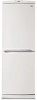
SERVICING
PRECAUTIONS
Air
Recharging
in Compressor
Test the refrigeration
by connecting
it electrically
before
refilling operation.
It is necessary
to ascertain
the function
of the meter-compressor
and identify the defects
immediately.
If defects have been found,
empty
the old
system of possible
R134a residue by breaking
off the end
of the extension
piece
at
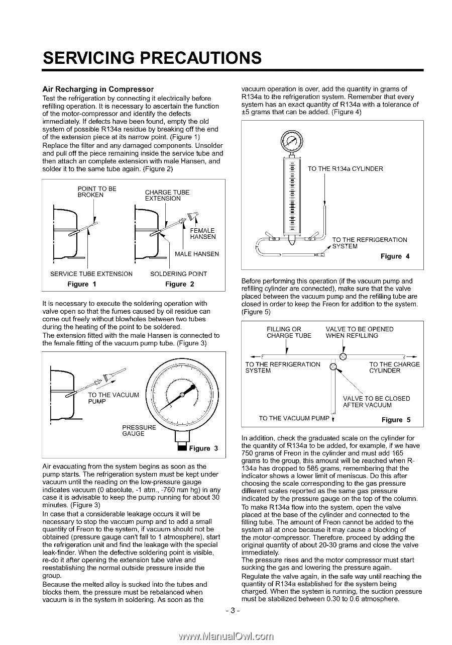
its narrow point. (Figure 1)
Replace the filter and any damaged
components.
Unsolder
and pull off the piece remaining
inside the service
tube and
then attach an complete
extension
with male Hansen,
and
solder it to the same tube again. (Figure 2)
POINT TO BE
BROKEN
SERVICE TUBE EXTENSION
CHARGE TUBE
EXTENSION
MALE HANSEN
SOLDERING
POINT
Figure
1
Figure
2
It is necessary
to execute
the soldering
operation
with
valve open so that the fumes caused
by oil residue can
come out freely without blowholes
between two tubes
during the heating of the point to be soldered.
The extension fitted with the male Hansen is connected
to
the female fitting of the vacuum
pump tube. (Figure 3)
UM
PRESSURE
GAUGE
igure
3
Air evacuating
from the system begins as soon as the
pump starts. The refrigeration
system must be kept under
vacuum
until the reading on the low-pressure
gauge
indicates
vacuum
(0 absolute,
-1 atm., -760 mm hg) in any
case it is advisable
to keep the pump running for about 30
minutes. (Figure 3)
In case that a considerable
leakage
occurs it will be
necessary
to stop the vaccum
pump and to add a small
quantity
of Freon to the system, if vacuum
should not be
obtained
(pressure
gauge can't fall to 1 atmosphere),
start
the refrigeration
unit and find the leakage
with the special
leak-finder.
When the defective
soldering
point is visible,
re-do it after opening the extension
tube valve and
reestablishing
the normal outside
pressure
inside the
group.
Because
the melted alloy is sucked into the tubes and
blocks them,
the pressure
must be rebalanced
when
vacuum
is in the system
in soldering.
As soon
as
the
vacuum
operation
is over, add the quantity
in grams of
R134a to the refrigeration
system.
Remember
that
every
system
has an exact quantity
of R134a with
a
tolerance
of
+5 grams that can be
added.
(Figure 4)
q\
i
TO TiE
R134a CYLINDER
'__
TOsTTHEEMR
E
F
RiGEF_lr_
N4
Before performing this operation
(if the vacuum pump and
refilling cylinder are connected),
make sure that the valve
placed between the vacuum pump and the refilling tube are
closed in order to keep the Freon for addition to the system.
(Figure 5)
FILLING OR
VALVE TO BE OPENED
CHARGE TUBE
WHEN REFILLING
TO THE
REFRIGERATION
TO THE CHARGE
SYSTEM
CYLINDER
VALVE
TO BE CLOSED
AFTER
VACUUM
TO THE VACUUM
PUMP
Figure
5
In addition, check
the
graduated
scale on the cylinder for
the quantity of R134a to be added, for example,
if we have
750 grams of Freon in the cylinder and must add 165
grams to the group, this amount will be reached
when R-
134a has dropped to 585 grams, remembering
that the
indicator shows a lower limit of meniscus.
De this after
choosing
the scale corresponding
to the gas pressure
different
scales reported
as the same gas pressure
indicated
by the pressure
gauge on the top of the column.
To make R134a flow into the system, open the valve
placed at the base of the cylinder and connected
to the
filling tube. The amount of Freon cannot
be added to the
system all at once because
it may cause a blocking of
the motor-compressor.
Therefore,
proceed
by adding
the
original
quantity
of about 20-30 grams
and
close the valve
immediately.
The pressure
rises and the motor compressor
must start
sucking
the gas and lowering
the pressure
again.
Regulate
the valve again, in the safe way until reaching
the
quantity
of R134a established
for the system being
charged.
When the system is running,
the suction pressure
must be stabilized
between 0.30 to 0.6 atmosphere.
-3-