LG LRBP1031W User Guide - Page 10
oros,'a c v
 |
UPC - 048231777223
View all LG LRBP1031W manuals
Add to My Manuals
Save this manual to your list of manuals |
Page 10 highlights
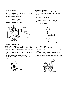
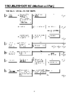
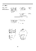
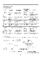
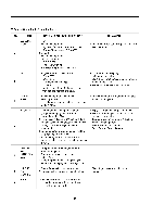
2 PTC AND OLP Normal operation of Compressor is mposs b e or poor. Separate the PTC-Starter from Compressor and measure the resistance between No. 5 and 6 (only RSIR type) or No. 4 and 5 of PTC-Stader with a Tester or Whistone Bridge. (Figure 21) Observation value is 220V/50Hz : 22§ _+30% 115V/60Hz : 6.8§ _+30% 240V/50Hz : 33§ _+30% 127, 220V/60Hz : 22§ +_3O% electric t Ccohmecpkonaennotsth. er . 'orost,'a c v or serveral hundreds §. Replace PTC-Starter. Separate the OLP from the _ Compressor and check the resistance value between two terminals of OLP with a Tester. (Figure 22) }_ Check another electric components. Replace OLP. Figure 21 Figure 22 -12-
-
 1
1 -
2
-
3
-
4
-
 5
5 -
 6
6 -
 7
7 -
 8
8 -
 9
9 -
 10
10 -
 11
11 -
 12
12 -
 13
13 -
 14
14 -
 15
15 -
16
-
17
-
18
-
19
-
20
-
21
-
22
-
23
-
24
-
25
-
26
-
27
-
28
-
29
-
30
-
31
-
32
-
33
 |
 |

2 PTC AND
OLP
Normal operation
of
Compressor
is
mposs b e or poor.
Separate
the
PTC-Starter
from Compressor and
measure the resistance
between No. 5 and 6 (only
RSIR type) or No. 4 and 5 of
PTC-Stader with a Tester or
Whistone Bridge.
(Figure 21)
Observation
value is
220V/50Hz
:
22§ _+30%
115V/60Hz
: 6.8§
_+30%
240V/50Hz
: 33§
_+30%
127, 220V/60Hz
: 22§
+_3O%
. 'oros,'a c v
t
or serveral
hundreds
§.
Separate
the OLP from the
Compressor
and check the
resistance
value between
two terminals
of OLP with
a Tester. (Figure 22)
_
Check another
electric components.
}_
Replace
OLP.
t Check another
electric
components.
Replace
PTC-Starter.
Figure
21
Figure
22
-12-