LG LST-4200A Service Manual
LG LST-4200A Manual
 |
View all LG LST-4200A manuals
Add to My Manuals
Save this manual to your list of manuals |
LG LST-4200A manual content summary:
- LG LST-4200A | Service Manual - Page 1
P/NO : 3829RVN007H SERVICE MANUAL JUNE, 2004 Printed in Korea MODEL : LST-4200A Digital Set Top Box SERVICE MANUAL INTRODUCTION: This manual is to let you know all service information, including parts, circuit control & maintenance and etc. You don't need to control mileage and the circuits - LG LST-4200A | Service Manual - Page 2
1. OVERVIEW PRODUCT SPECIFICATION 1-2 PARTS NAME 1-3 CHAPTER 2. EXPLODED DIAGRAM CABINET AND MAIN FRAME 2-1 PACKING ACCESSORIES 2-3 (INCLUDING REMOTE-CONTROLLER) CHAPTER 3. CIRCUIT SW_UPDATE Method 3-1 Diagnostic S/W Application 3-5 Flow Chart for Repair 3-7 1. Power Operation 3-7 2. Audio - LG LST-4200A | Service Manual - Page 3
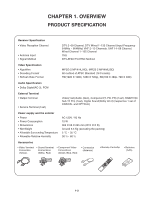
CHAPTER 1. OVERVIEW PRODUCT SPECIFICATION Receiver Specification • Video Reception Channel • Antenna Input • Signal Method DTV 2~69 Channel, DTV Wired 1~135 Channel (Input Frequency 54MHz ~ 864MHz) VHF 2~13 Channels, UHF 14~69 Channel, Wired Channel 1~135 Channel 75Ω DTV-ATSC/TV-NTSC Method Video - LG LST-4200A | Service Manual - Page 4
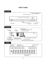
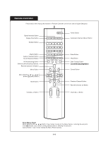
Front Side PARTS NAME Menu Selection, Channel Selection, Volume Control Button Remote Controller Receiver Power Button Back Side Antenna Input Terminal Terminal for Service Display Output Selection Button Menu Button Cancel Button Enter Button Component Video (1080i/720p/480p/480i) Output - LG LST-4200A | Service Manual - Page 5
Remote-Controller Power Button Press button with it facing the receiver of Remote Controller on the front side of Digital Settopbox. Power Button Signal InPteonwsietyr BBuuttttoonn Display Size Button Power Button Number Button Power Display Size Signal Intensity Automatic Channel Add-on Power - LG LST-4200A | Service Manual - Page 6
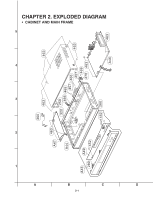
CHAPTER 2. EXPLODED DIAGRAM • CABINET AND MAIN FRAME 5 4 3 2 1 A 463 A47 A44 A43 280 A49 452 300 463 463 320 250 466 465 457 466 457 463 469 470 463 B 2-1 C 452 260 463 A46 D - LG LST-4200A | Service Manual - Page 7
SERVICE PARTS LIST S AL LOCA. NO. LG PART NO. DESCRIPTION 250 3110R-P020A CASE 300 6410REHK02A POWER ,TOTAL SPECIFICATION VCR LSS-2300 TOP(SKYLIFE STB) KJP LST-3000) MAIN(LST-3000) VCR BACK(LST-3000) PRESS SPECIAL(3X8 BK.) VCR LST-3000 SPECIAL LST-3100Z TIMER TOTAL SETTOP BOX LST-3100 SMPS LST - LG LST-4200A | Service Manual - Page 8
• PACKING ACCESSORIES (INCLUDING REMOTE CONTROLLER) 822 SMART CARD 808 BATTERY 900 REMOCON 801 OWNER'S MANUAL 803 PACKING 811 PLUG ASS'Y 1WAY 812 PLUG ASS'Y 2WAY 820 PLUG ASS'Y(3WAY) 813 S-VIDEO CABLE 806 RF CABLE 823 TELEPHONE LINE 804 PACKING - LG LST-4200A | Service Manual - Page 9
• SERVICE PARTS LIST FOR PACKING ACCESSORIES S AL LOCA. NO. LG PART NO. DESCRIPTION 801 3835RB0001K INSTRUCTION ASSEMBLY 802 3890R-C120L 6611R3G001B PLUG ASSEMBLY 900 6711R1N158A REMOTE CONTROLLER ASSEMBLY SPECIFICATION SETTOP BOX LST-3000_KOR LST-3000 DOM SWM3-A STB SKYLIFESTB 0.02 60 EPS - LG LST-4200A | Service Manual - Page 10
can be used, but TeraTerm is advised to use. 2. Set "Setup © Serial Port" like the display. (But, Port should be properly setup, depending on the user environment.) 3. Set up properly "Setup © Terminal" like the Figure. 3-1 - LG LST-4200A | Service Manual - Page 11
After all set-up, press "b(a small letter)" in the terminal and charge power of STB. 5. It is possible to download application when the display is same with downloading command language like the above Figure and then press Enter again. 7. STB can download application program at this condition. 3-2 - LG LST-4200A | Service Manual - Page 12
8. Another display as the above is generated when selecting "File © Send File" in the downloadable condition. Find and open ram.biz file to start downloading . 9. The downloading process is shown on the display and it completes after around 2 minutes. After complete downloading process, a message to - LG LST-4200A | Service Manual - Page 13
10. The above message comes out when the application program is successfully written on the Flash. It operates normally either when plugging in again or inputting "boot flash" in this display. (If there is no response, input a command language again.) 3-4 - LG LST-4200A | Service Manual - Page 14
material. 1) To enter into the Hardware Diagnostic Method After connecting serial cable through service ports of PC and LST-3100A, press "t(a small letter)" of keyboard and at the same time turn on power of LST-3100. The initial screen of hardware diagnostic comes out on the TeraTerm Terminal when - LG LST-4200A | Service Manual - Page 15
outputs "PASS" when the condition of all part is Normal and "FAIL" when is abnormal. - Log out the Self-Diagnostics when inputting any key and STB works normally. [Figure 2] 3-6 - LG LST-4200A | Service Manual - Page 16
Flow Chart for Repair 1. POWER OPERATION (1) No 5.0VA No 5.0VA YES NO Is the F101 normal? Replace the D105. Replace the D109. Replace the D110. Replace the D108. YES Is the D107 NO Normal? YES Power Line of Main PCB is short Replace the D107. (2) No 5.0V NO 5.0V YES Is there about 5.4V - LG LST-4200A | Service Manual - Page 17
(4) No 5.0VA Is there about 5.4V at the IC152 pin1? YES Is there about 3.3V~ 5V NO at the IC152 pin4? YES Check the IC152 NO and Replace Check or Replace the D106 Check the 'PWR CTL "H"' signal from µ-com (5) No 9V No 9V YES Is there about 13V NO at the IC154 pin1? YES Is there about 3.3V~ NO 5V - LG LST-4200A | Service Manual - Page 18
(8) No 30VA No 30VA YES Is The ZD110 NO Normal? YES IsCRThehepeclZakDcae11nt0dheNoDrm1a1l0? Replace the ZD101 (9) No VFD No VFD YES Is The R123 NO Normal? YES NO Is The D107 Normal? YES Is The ZD102 NO Normal? YES Check and Replace the D108 Replace the R123 Replace the R107 Replace the - LG LST-4200A | Service Manual - Page 19
(IC203(G3)? YES Does 3.072MHz clock come from NO R230? YES Does 48kHz clock come from R229? NO Check Power Supply part. Check around circuits of IC203. 3-10 - LG LST-4200A | Service Manual - Page 20
Fig.01 Data coming from HA_DACLRCH IC203(G3) Fig.02 R3.072MHz clock coming from R230 Fig.03 48KHz clock coming from R299 3-11 - LG LST-4200A | Service Manual - Page 21
. Is 5V supplied into IC400 NO (10, 16, 49, 63)? YES NO Is 8V supplied into IC400(31)? YES Check Power Supply part. Is 12V supplied into IC401(1)? YES Check Power Supply part. Is 18.432MHz Clock supplied to NO IC400(54,55)? YES NO Is data pulse supplied to IC400(6)? YES - LG LST-4200A | Service Manual - Page 22
3) Check IC402 and its around circuits. NO Is 9V supplied to IC402(8)? YES Does analog signal come from NO IC402(1, 7)? Check Power Supply part. Check IC402 and its around circuits. 4) Check the output jacK and its around circuits. Check CN301 and its around circuits. 3-13 - LG LST-4200A | Service Manual - Page 23
(2) When there is no NTSC Audio NO Does ATSC audio sound? YES NO Does SIF signal go into Q400(2)? YES Does SIF signal go into IC400(50)? NO (Fig. 05) YES Does analog audio signal sound at NO IC400(17.18)? Go to "1. When there is no NTSC Audio." to check. Check IC500. Check Q400. Check IC400 and its - LG LST-4200A | Service Manual - Page 24
CN400(2)? YES Check CN400 and its around circuits. Go to "1. When there is no NTSC Audio." to check. Check IC203i and its around circuits. Check Power Supply part. Fig.06 SPDIF Output 3-15 - LG LST-4200A | Service Manual - Page 25
SPDIF pulse come from NO IC203(F3)? YES Does SPDIF signal come from NO Q401(1)? YES Check CN301(S4,G4) and its around circuits. Check Power Supply part. Check IC203 and its around circuits. Check Power Supply part. Fig.07 SPDIF Output 3-16 - LG LST-4200A | Service Manual - Page 26
(5) When there is no NTSC SPDIF NO Is NTSC audio working normally? YES Does 18.432MHz clock come from NO IC400(57)? YES Does data pulse come from NO IC400(5)? Go to "2. When there is no NTSC Audio." to check. Check IC400. Check IC400. Fig.08 18.432MHz clock coming from IC400(57) 3-17 - LG LST-4200A | Service Manual - Page 27
source working normally? YES NO Is system clock working? YES Is each reset signal normally NO generated when charging power? YES Is the CS(chip selection) signal of NO flash parts normal? YES Is I2 C(SDA, SCL) channel normally NO working? YES Is it coming - LG LST-4200A | Service Manual - Page 28
supplied to pin 38 of IC103, NO IC104 and to pin 1of IC107, IC108? Check power bus. IC503 : 2.5V / IC501 : 3.3V Check power bus. IC503: 3.3V (B) YES Does crystal of X100 generate NO 10MHz? YES Is clock of pin 28 of IC110 outputted NO at 60MHz? < - LG LST-4200A | Service Manual - Page 29
.03> YES Is reset signal generating at NO pin 93 of IC110? YES Is reset signal generating at pin 10 of IC104 NO when pressing power key? Check IC100. Check IC101. Check IC110. Check IC101. Fig.03 Fig.04 3-20 - LG LST-4200A | Service Manual - Page 30
(D) YES Is signal generating at pin 26 of NO IC103, IC104 when charging power at the first time? YES Is signal generating continuously at NO pin 26 of IC103, IC104 when charging power at the first time? YES Was the booting process normally NO completed? Check IC110. Check 1C103 - LG LST-4200A | Service Manual - Page 31
(E) YES Are IIC SCL and SDA signal from pin 60 and pin NO 61 generated normally? YES Are IIC SCL, which is connected between IC11O NO and pin 1/pin 2 of IC102, and SDA signal outputted? YES Are IIC SCL and SDA signal gener- NO ated into 6 pin and pin 7 of IC102? Check IC110. - LG LST-4200A | Service Manual - Page 32
(G) YES Is setup of RS-232C Port normal? NO (Baudrate, Parity, Data Bit, Stop Bit) YES Is there pin 11 TxD signal of IC102? NO YES NO Is there pin 12 RxD signal of IC102? RS-232C port setup modification Check IC110 and IC105. Check IC110 and IC105. Fig.08 3-23 - LG LST-4200A | Service Manual - Page 33
4. VIDEO part START YES NO There is no HV sync OUT? YES NO Is there problem at OSD? YES NO Is there problem at Main Picture? YES NO Is there problem at AV output? YES END (A) (B) What is the main picture source? (C1). (C2). (D) 3-24 - LG LST-4200A | Service Manual - Page 34
Display Clock(IC206(7)) NO supplied into HD2? YES Switch the Display Color into RGB/DVI. Check HV sync. Is there any problem? YES NO END Check Power Supply part. Check IC204(5) and IC206(1). YES Check IC204(1,8) and X200 when it is sine curve form « 27MHz clock.? - LG LST-4200A | Service Manual - Page 35
Fig.02 VCXO 27MHz Clock Fig.03 Crystal 27MHz Clock Fig.04 H-sync Signal Fig.05 V-sync Signal 3-26 - LG LST-4200A | Service Manual - Page 36
. Check Power Supply part. In the case of (C1) _ DTV, NO Check if there is input stream. Is there any problem? NO Is there decoding problem? NO END YES NG Check tuner part. Check signal intensity. Check if system clock 27MHz comes from IC206(9), when signal is normal. OK Check HD 2 interrupt - LG LST-4200A | Service Manual - Page 37
Fig.06 Input Stream to IC400 Fig.07 Interrupt Request Signal on HD2(F11) 3-28 - LG LST-4200A | Service Manual - Page 38
.08> OK NG Check NTSC decoder. NO Is analog component on the Mute NO mode? NO Is analog component on the Mute mode? Check tuner block(TU300) • power check; L300 5V Analog input: IC301(44) • Reference clock oscillation : X300 • Pixel clock: 13.5MHz continuous Clock in IC301 (28). - LG LST-4200A | Service Manual - Page 39
Fig.09 X300 Reference Clock Fig.12 NTSC Decoder Vsync Output(Top), Field ID(bottom) Fig.10 NTSC Decoder Pixel Clock Fig.11 NTSC Decoder Hsync Output 3-30 - LG LST-4200A | Service Manual - Page 40
(D) YES Is NTSC mute signal at low? NO NG Check HD-II NTSC encoder part. Check if Q308(2),Q309(2) and Q310(2) are in the low. Otherwise, check IC208(7). Check NTSC encoder pixel clock: IC204(7) Check NTSC analog output buffer part. OK END Fig.13 27MHz NTSC Encoder Pixel Clock 3-31 - LG LST-4200A | Service Manual - Page 41
5. DVI Part Start YES NO Is DVI cable connected? YES Is DVI ICON set up on the front NO panel? YES NO Is 480P picture shown? YES NO Are 720P & 1080I pictures shown? YES NO Is 480I picture shown? YES END Connect DVI cable. Set up on the DVI using Display Format Key. Check IC302(57(IDCK - LG LST-4200A | Service Manual - Page 42
Fig.01 DVI Output in 480p Fig.02 DVI Output in 720p Fig.03 DVI Output in the 1080i Even Field Fig.04 DVI Output 1080i Odd Field Fig.05 DVI Output 480i Even Field Fig.06 DVI Output 480i Even Field 3-33 - LG LST-4200A | Service Manual - Page 43
used) High : Normal, Low : Abnormal YES Check output data of tuner(IC500). NO (Fig. 01) (pin 28,29,30,31,32,33,34,35), packet clock ( Fig.02)(pin 27) and byte clock(pin 36) (Fig.03). YES END Check the power line, referring to circuit diagram. (+5V_Alive, +5V, +30V, +1.8, +3.3V) Check - LG LST-4200A | Service Manual - Page 44
Fig.01 IC500 (28,29,30,31,32, 33,34,35) VSB Data Output. Fig.02 IC500(27) VSB Data Packet Clock Fig.03 IC500(36) VSB Data Byte Clock 3-35 - LG LST-4200A | Service Manual - Page 45
R511 and NO earth. 5V : Abnormal(Bad), 1V ( below) : Normal YES Check video output signal of NIM NO Tuner Tuner(IC500)(pin 16, Fig.04). YES END Check power line, referring to circuit diagram. (+5V_Alive, +5V, +30V, +1.8, +3.3V) Check antenna connection condition. Replace Q501, Q502. Replace - LG LST-4200A | Service Manual - Page 46
Whole Block Diagram 1. WHOLE BLOCK DIAGRAM - 1 Board-to-Board Connection AC220V SMPS Board 1 PWR_CTRL 1 2 30V 2 3 GND 3 4 12V 4 5 9V 5 6 GND 6 7 5V 7 8 5V 8 9 3.3V 9 10 3.3V 10 11 GND 11 12 -28V 12 13 GND 13 14 FD(-)/-24V 14 15 FD(+)/-21.5V 15 MAIN Board GND IR_DATA - LG LST-4200A | Service Manual - Page 47
TUNER IC500 Loop Through NTSC AUDIO Tuner Controller VFD IR Receiver Key Scan Key Block NTSC VIDEO IC301 VIDEO PIXEL DECORDER (VPX3326E) YCbCr ATSC TP IC200 TP Demux Video Decoder Audio Decoder Format Converter VDP (LGDT1102A : HD Out VCR Out AC220V SMPS Power Control +30V +12V +9V + - LG LST-4200A | Service Manual - Page 48
NIM TUNER : Digital Video Signal : Digital Audio Signal IC500 Loop Through Tuner Controller VFD IR Receiver Key Scan Key Block NTSC VIDEO IC301 VIDEO PIXEL DECORDER (VPX3226E) YCbCr AC220V SMPS Power Control Decoder Format Converter VDP (LGDT1102A : HD-II) Line Driver (74HC540) IC202 - LG LST-4200A | Service Manual - Page 49
4. POWER BLOCK DIAGRAM BD101 R105 + C103 NOISE FILTER BLOCK (C101,L101, C102) ! FUSE (F101) ! BR BL (BK)(WH) ! Y-CAP C113 ! Y-CAP C112 SNUBBER BLOCK (D102,C105 - LG LST-4200A | Service Manual - Page 50
CONTROL BLOCK DIAGRAM IC300 I2C Ext. (82B715) IC106 EEPROM (25LC256) IC302 DVI Transmitter (Sil 170) TUNER VSB IC TUNER PLL NIM TUNER , IR_DATA Sys Reset (KIA7029 & 74HC14) IC100, IC101 GCS6/SCS0 DATA BUS[0-15] DMA control A[2-20] Addr[23,22,13-2] DQM0/DQM1/WE/CA S/RAS/CLK/CKE FLASH ROM ( - LG LST-4200A | Service Manual - Page 51
6. AUDIO PROCESSING Block Diagram IC200 HA_DACLRCH HA_DACLRCK HA_AUDCLKOUT IC400 AUDIO DAC (MSP4448G) Left Audio Out Right Audio Out IC402 Low Pass Filter (MC33078) HD2 (LGDT 1102A) IC110 Left Audio Out Right Audio Out CPU (S3C44B0X) AUDIO_MUTE_CTRL TR Buffer Q405, Q406, Q407, Q408 - LG LST-4200A | Service Manual - Page 52
FL300~302 LPF (TOKO 25M) X 3 IC303 AMP (LMH6683) Q311~Q316 Buffer TR YPbPr BYPBPR_MUTE_CTRL BRGB_MUTE_CTRL HP_CVBS_OUT HP_SVIDEO_Y HP_SVIDEO_C Q308~Q310 MUTE control TR IC304 AMP (LMH6683) BVCR_MUTE_CTRL I2C Ext. (82B715) IC300 DVI Out RGB RGB Video Out YPbPr Video Out VCR Out S-Video - LG LST-4200A | Service Manual - Page 53
Circuit Diagram 1. POWER Circuit Diagram No Power BD101, R105 are Defective -30VA No Power D108 is Defective 12V No Power D125 is Defective No Power D102 is Defective No Digitron appeared D107, R123, ZD102 are Defective 3.3V No Power D105 is Defective 30VA No Power D110 is Defective Switching - LG LST-4200A | Service Manual - Page 54
2. SYSTEM Circuit Diagram 3-53 3-54 - LG LST-4200A | Service Manual - Page 55
3. VIDEO Circuit Diagram _1 3-55 3-56 - LG LST-4200A | Service Manual - Page 56
4. VIDEO Circuit Diagram _2 3-57 3-58 - LG LST-4200A | Service Manual - Page 57
5. AUDIO CIRCUIT DIAGRAM 3-59 3-60 - LG LST-4200A | Service Manual - Page 58
6. FRONT END & POWER CIRCUIT DIAGRAM 3-61 3-62 - LG LST-4200A | Service Manual - Page 59
7. FRONT BOARD CIRCUIT DIAGRAM 3-63 3-64 - LG LST-4200A | Service Manual - Page 60
PARTS LAYOUT 1. DIGITAL MAIN PARTS LAYOUT(TOP) 3-65 3-66 - LG LST-4200A | Service Manual - Page 61
2. DIGITAL MAIN PARTS LAYOUT (BOTTOM) 3-67 3-68 - LG LST-4200A | Service Manual - Page 62
3. KEY(RIGHT) PARTS LAYOUT LOCATION GUIDE 4. SMPS(POWER) PARTS LAYOUT LOCATION GUIDE 3-69 3-70 - LG LST-4200A | Service Manual - Page 63
- LG LST-4200A | Service Manual - Page 64
586-008B HOLDER SPECIFICATION REMARKS VCR LSS-2300 TOP(SKYLIFE STB) KJ-10W/NISPT-2(ST-HS:80MM) WIT + 2 D3.0 L8.0 MSWR3/FN TB ROUN SPECIAL (3X10 B.K) D5.1 L7.0 STS 430 4 D3/8-16 NO RULE BSP/BN,BSW/ NO RULE D12.0 SUS 304 SETTOP BOX LST-4200A_LGEUS_ENG LST-4200 AA1ULL SWM3-A STB SKYLIFESTB 0.02 60 - LG LST-4200A | Service Manual - Page 65
MODEL : LST-4200A AA1ULL(LGEUS) NSP : Not avallable as service parts. RUN DATE :10-JUNE-04 S AL LOCA. NO. IC101 IC102 IC103 IC103 IC152 IC152 IC153 IC153 IC154 IC154 IC155 IC155 IC155 IC156 IC156 L101 - LG LST-4200A | Service Manual - Page 66
: LST-4200A AA1ULL(LGEUS) NSP : Not avallable as service parts. C103 C104 C105 C106 C107 LG PART NO. DESCRIPTION 0CE4764F638 6712R0838GA REMOTE CONTROLLER RECEIVER 0LR0102K035 M/L T.C F/S 0CH4220K412 CAPA,CHIP CERAMIC M/L T.C F/S SPECIFICATION 47M SRA/SS 16V M FM5 TP(5) 1SS133 DETECT,SW - LG LST-4200A | Service Manual - Page 67
: LST-4200A AA1ULL(LGEUS) NSP : Not avallable as service parts. C235 C236 C237 C238 C239 LG PART NO. 0CH4220K412 0CH4220K412 .c CAPACITOR,FIXED CERAMIC(Temp.c CAPACITOR,FIXED CERAMIC(Temp.c CAPACITOR,FIXED CERAMIC(Temp.c SPECIFICATION 22P 50V J COG 1.6X0.8 R/TP 22P 50V J COG 1.6X0.8 R/TP - LG LST-4200A | Service Manual - Page 68
: LST-4200A AA1ULL(LGEUS) NSP : Not avallable as service parts. C311 C312 C313 C314 C315 LG PART NO. 0CH1104K512 0CH1104K512 ELECTROLYTI CAPACITOR,FIXED CERAMIC(Temp.c CAPACITOR,FIXED CERAMIC(Temp.c CAPACITOR,FIXED CERAMIC(Temp.c SPECIFICATION 0.1UF 50V 10% B(5YP) 1608 R/TP 0.1UF 50V 10% B(5YP) - LG LST-4200A | Service Manual - Page 69
MODEL : LST-4200A AA1ULL(LGEUS) NSP : Not avallable as service parts. RUN DATE :10-JUNE-04 S AL LOCA. NO. C316 C317 C318 C319 C320 C321 C322 C323 C324 C325 C326 C327 C328 C329 C330 C331 - LG LST-4200A | Service Manual - Page 70
MODEL : LST-4200A AA1ULL(LGEUS) NSP : Not avallable as service parts. FL307 FL308 FL309 FL310 LG PART NO. 0CH1104K512 0CH8476F611 ),EMC FILTER(CIRC),EMC FILTER(CIRC),EMC FILTER(CIRC),EMC FILTER(CIRC),EMC FILTER(CIRC),EMC SPECIFICATION 0.1UF 50V 10% B(5YP) 1608 R/TP 47UF 16V M 85STD(CYL) R/TP SAM - LG LST-4200A | Service Manual - Page 71
LST-4200A AA1ULL(LGEUS) NSP : Not avallable as service IC,MEMORIES IC,MICRO CONTROLLER IC,MEMORIES IC,MEMORIES POWER MANAGEMENT IC,MOTOROLA TUNER IC,POWER MANAGEMENT IC,POWER MANAGEMENT IC,POWER ,CHIP INDUCTOR,CHIP SPECIFICATION REMARKS BMK400 TA BUFFE LGDT1102 HD2 LG IC SBGA-432PI CY24212SC - LG LST-4200A | Service Manual - Page 72
MODEL : LST-4200A AA1ULL(LGEUS) NSP : Not avallable as service parts. RUN R126 R127 R128 R129 R130 R131 LG PART NO. 0LCCE00005E 0LCCE00005E 0LCCE00005E GLAZED(CHIP) RESISTOR,METAL GLAZED(CHIP) RESISTOR,METAL GLAZED(CHIP) SPECIFICATION HB-1M3216-102JT ,CHIP3216 CERA HB-1M3216-102JT ,CHIP3216 CERA - LG LST-4200A | Service Manual - Page 73
LST-4200A AA1ULL(LGEUS) NSP : Not avallable as service R210 R211 R212 R213 LG PART NO. 0RH4701C622 (CHIP) RESISTOR,METAL GLAZED(CHIP) RESISTOR,METAL GLAZED(CHIP) RESISTOR,METAL GLAZED(CHIP) RESISTOR,METAL GLAZED(CHIP) SPECIFICATION 4.7K OHM 1 / 16 W 1608 5.00% D 4.7K OHM 1 / 16 W 1608 5.00% - LG LST-4200A | Service Manual - Page 74
LST-4200A AA1ULL(LGEUS) NSP : Not avallable as service parts R3053 R3054 R3055 LG PART NO. GLAZED(CHIP) RESISTOR,METAL GLAZED(CHIP) RESISTOR,METAL GLAZED(CHIP) RESISTOR,METAL GLAZED(CHIP) RESISTOR,METAL GLAZED(CHIP) SPECIFICATION 22 OHM 1 / 16 W 1608 5.00% D 4.7K OHM 1 / 16 W 1608 5.00% D - LG LST-4200A | Service Manual - Page 75
LST-4200A AA1ULL(LGEUS) NSP : Not avallable as service parts R3128 R3129 R3130 LG PART NO. METAL GLAZED(CHIP) RESISTOR,METAL GLAZED(CHIP) RESISTOR,METAL GLAZED(CHIP) RESISTOR,METAL GLAZED(CHIP) RESISTOR,METAL GLAZED(CHIP) SPECIFICATION 0 OHM 1 / 16 W 1608 5.00% D 0 OHM 1 / 16 W 1608 5.00% D 0 - LG LST-4200A | Service Manual - Page 76
: LST-4200A AA1ULL(LGEUS) NSP : Not avallable as service parts ZD100 ZD101 ZD200 ZD300 LG PART NO. 0RH0682C622 ,CRYSTAL RESONATOR,CRYSTAL RESONATOR,CRYSTAL RESONATOR,CRYSTAL DIODE,RECTIFIERS DIODE,RECTIFIERS DIODE,RECTIFIERS DIODE,ZENER SPECIFICATION 68 OHM 1 / 16 W 1608 5.00% D 68 OHM 1 / 16
-
 1
1 -
 2
2 -
 3
3 -
 4
4 -
 5
5 -
 6
6 -
 7
7 -
8
-
9
-
10
-
11
-
12
-
13
-
14
-
15
-
16
-
17
-
18
-
19
-
20
-
21
-
22
-
23
-
24
-
25
-
26
-
27
-
28
-
29
-
30
-
31
-
32
-
33
-
34
-
35
-
36
-
37
-
38
-
39
-
40
-
41
-
42
-
43
-
44
-
45
-
46
-
47
-
48
-
49
-
50
-
51
-
52
-
53
-
54
-
55
-
56
-
57
-
58
-
59
-
60
-
61
-
62
-
63
-
64
-
65
-
66
-
67
-
68
-
69
-
70
-
71
-
72
-
73
-
74
-
75
-
76
 |
 |
MODEL : LST-4200A
MODEL : LST-4200A
SERVICE MANUAL
P/NO : 3829RVN007H
JUNE, 2004
Printed in Korea
Digital Set Top Box
SERVICE MANUAL
INTRODUCTION:
This manual is to let you know all service information, including parts, circuit control & maintenance and etc.
You don’t need to control mileage and the circuits except special case.That’s why they are already controlled
in the production stage at factory, which is required the high precision. When servicing the unit, please follow
this manual.
SAFETY PRECAUTIONS
•
Before servicing the unit, read and observe the safety precautions to service it properly and to prevent you
from any accident or danger.
•
Caution is divided into “Warning” and “Caution” as follows.
“Warning”: It may cause serious injury or even to death if you violate it.
“Caution”: It may cause light injury or any damage to the unit if you violate it.