LG LST-4200A Service Manual - Page 16
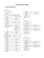
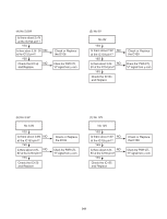
Flow Chart for Repair
 |
View all LG LST-4200A manuals
Add to My Manuals
Save this manual to your list of manuals |
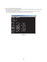
Page 16 highlights
Flow Chart for Repair 1. POWER OPERATION (1) No 5.0VA No 5.0VA YES NO Is the F101 normal? YES Is the BD101 NO normal? YES Is the R105 NO Normal? YES Is Vcc (13V - 16V) NO supplied to IC101 Pin7? YES Replace the F101. (Use the same Fuse) Replace the BD101. Replace the R105. Is the D103 normal? NO Check or Replace the D103. Are the D106 NO normal? YES Is there about 2.5V NO at the IC103 Pin1? YES Is the D105 NO normal? YES Is the D109 NO normal? YES Is the D110 NO normal? YES Is the D108 NO Normal? YES Replace the D106. Replace the IC103. Replace the D105. Replace the D109. Replace the D110. Replace the D108. YES Is the D107 NO Normal? YES Power Line of Main PCB is short Replace the D107. (2) No 5.0V NO 5.0V YES Is there about 5.4V NO at the IC152 pin1? YES Is there about 3.3V~5V NO at the IC152 pin4? YES Check the IC152 and Replace Check or Replace the D106 Check the 'PWR CTL "H"' signal from µ-com (3) No 3.3V No 3.3V YES Is there about 3.8V NO at the IC153 pin1? YES Is there about 3.3V~ NO 5V at the IC153 pin4? YES Check the IC153 and Replace Check or Replace the D105 Check the 'PWR CTL "H"' signal from µ-com 3-7
-
 1
1 -
2
-
3
-
4
-
5
-
6
-
7
-
8
-
9
-
10
-
 11
11 -
 12
12 -
 13
13 -
 14
14 -
 15
15 -
 16
16 -
 17
17 -
 18
18 -
 19
19 -
 20
20 -
 21
21 -
22
-
23
-
24
-
25
-
26
-
27
-
28
-
29
-
30
-
31
-
32
-
33
-
34
-
35
-
36
-
37
-
38
-
39
-
40
-
41
-
42
-
43
-
44
-
45
-
46
-
47
-
48
-
49
-
50
-
51
-
52
-
53
-
54
-
55
-
56
-
57
-
58
-
59
-
60
-
61
-
62
-
63
-
64
-
65
-
66
-
67
-
68
-
69
-
70
-
71
-
72
-
73
-
74
-
75
-
76
 |
 |
