LG LT1010C Owners Manual - Page 17
To,p_event injury o,rstrain, use p,ro_r
 |
View all LG LT1010C manuals
Add to My Manuals
Save this manual to your list of manuals |
Page 17 highlights
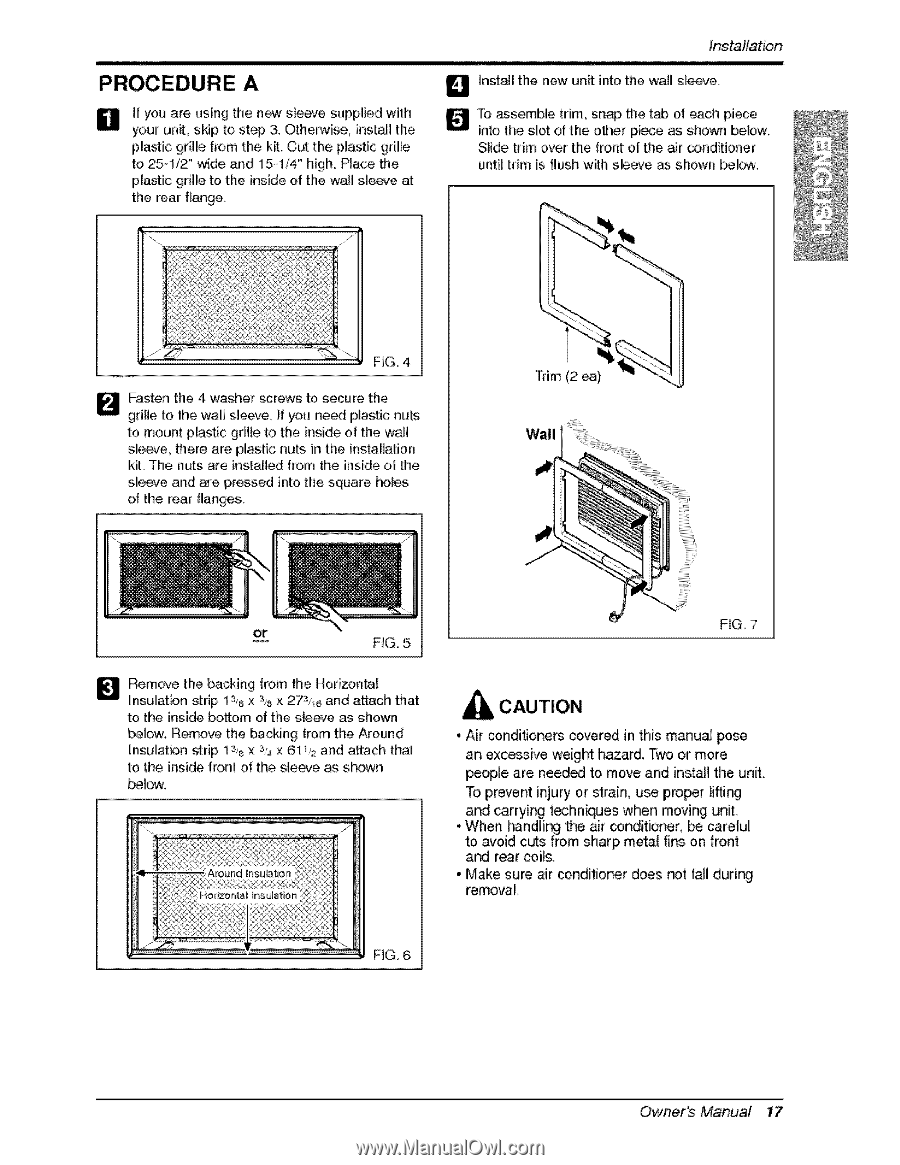
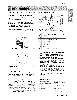
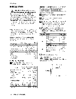
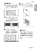
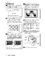
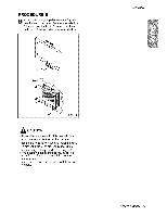
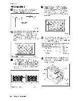
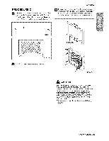
PROCEDURE A B ff you are using the new sleeve supplied with your unit, skip to st_ & Otherwise, instalil the p!iastic 9d!le from the kR. Cut the p_astic gri!le to 251/2" wide and 15d/4 ° high. Place the plastic grille to the inside of the wall smeeve at the rear flange. tn$i_lJatton _ insta]_ the new unff into the waU sleeve. To assemble trim, snap the tab of each piece into the sllot of the other pii_e as shown belo.w_ S[i,de. trim over the, front: of the _r conditioner uinti_trim is flush with s_eeve as, shown _. FIG_4, _ asten the 4 washer _rews to, secure the gdHe to the wa_l sleeve, if you need [plastic nuts to mount pUastic grNie to the inside of the wall sle_e, #'1ere are plastic nuts in the ins_flation kit_ The r_uts are ingtaHed ffo,m the iinside of the sleeve and are press_ into the square holes o_ the rear flanges. FiG, 7 _ emove the backing [rom the Ho,dzontal insulation strip lSs x s,_x 27s,_ and a_ach that to the inside bottom of the siege as shown _low: Remove the _cking from the Around hsulation strip Is,8 x s,,4x 61 _,_and attach that to the inside front ot the sleeve as shown _low: , Air ,corlditione_ covered in this manu,a] _se an exc_sive 'weigM hazard, Two or more pe_le, are need_ to move and install the unit. To,p_event injury o,rstrain, use p,ro_r _i_ and carryir_ t_hniques when moving unit. and rear coils, • M_e sure air conditio,ner ,does _t fa_lduring removal FiG,6 Owne, s MaDiual 17
-
 1
1 -
2
-
3
-
4
-
5
-
6
-
7
-
8
-
9
-
10
-
11
-
 12
12 -
 13
13 -
 14
14 -
 15
15 -
 16
16 -
 17
17 -
 18
18 -
 19
19 -
 20
20 -
 21
21 -
 22
22 -
23
 |
 |