LG M2400HR Service Manual
LG M2400HR Manual
 |
View all LG M2400HR manuals
Add to My Manuals
Save this manual to your list of manuals |
LG M2400HR manual content summary:
- LG M2400HR | Service Manual - Page 1
SERVICE MANUAL CAUTION - BEFORE SERVICING THE UNIT, READ THE SAFETY PRECAUTIONS IN THIS MANUAL. - ONLY FOR AUTHORIZED SERVICE. Thermostat Auto Swing Off On Fan Operation Off Warmer Low Heat Cooler WBaeiftoTrehrReeesMtainrtuintegs High Heat Fan Low Cool High Cool MODELS: R1804H/M2400HR - LG M2400HR | Service Manual - Page 2
Air Conditioner Service Manual TABLE OF CONTENTS Safety Precautions...3 Dimensions...5 Installation ...6 How to instructions...13 Mechanical parts ...13 Air Handling Parts ...14 Electrical Parts ...15 Refrigeration cycle ...18 Troubleshooting guide...21 Piping System ...21 Troubleshooting guide - LG M2400HR | Service Manual - Page 3
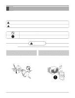
. Be sure not to do. Be sure to follow the instruction. s Installation WARNING Do not use damaged power cord plugs, or a loose socket. Always use the power plug and socket with the ground terminal. • There is risk of fire or electric shock. • There is risk of electric shock. Service Manual 3 - LG M2400HR | Service Manual - Page 4
Safety Precautions Do not modify or extend the power cord. • There is risk or fire or electric shock. Do not install, remove, or re-install the unit by yourself. • There is risk of fire, electric shock, explosion, or injury. Be cautious when unpacking and installing the product. Do not store or - LG M2400HR | Service Manual - Page 5
Dimensions Symbols Used in this Manual This symbol alerts you to the risk of electric shock. This symbol alerts you to hazards that could cause harm to the air conditioner. NOTICE This symbol indicates special notes. Outside Dimensions 675(770) 660 Dimensions 428 Service Manual 5 - LG M2400HR | Service Manual - Page 6
Installation INSTALLATION How to Install the unit 1. To avoid vibration and noise, make sure the unit is installed securely and firmly. 2. Install the unit where the sunlight does not shine directly on the unit. If the unit receives direct sunlight, build an awning to shade the cabinet. 3. There - LG M2400HR | Service Manual - Page 7
bar Foam-PE (Adhesive-Backed) Foam strip Foam-PE (Plain-Back) (Adhesive-Backed) Left frame curtain Frame guide(2) Window locking bracket Sill bracket(2) Support bracket(2) Right frame curtain Type A (14) Type B (7) Type C (5) Type D (2) Carriage Bolt (2) Lock Nut (4) Service Manual 7 - LG M2400HR | Service Manual - Page 8
Auto Swing Off On Fan Operation Off Warmer Low Heat Cooler WBaeiftoTrehrReeesMtairntuintegs High Heat Fan Low Cool High Cool Top retainer bar 6. Insert the Frame guides into the bottom of the cabinet. 7. Insert the Frame Curtain into the Top retainer bar and Frame - LG M2400HR | Service Manual - Page 9
the center of the window stool between the side window stop moldings. Loosely attach the sill bracket to the support bracket using the carriage bolt and the lock nut. 2. Attach the sill bracket to the window sill Foam-PE Figure 8 Sash track Figure 9 Front Angle Screw(Type B) Service Manual 9 - LG M2400HR | Service Manual - Page 10
Installation 5. Pull each Frame curtain fully to each window sash track, and pull the bottom window sash down behind the Top retainer bar until it meets. Screw(Type C) 6. Attach each Frame curtain the window sash by using screws (Type C). (See Fig. 10) Figure 10 7. Slide the unit into the - LG M2400HR | Service Manual - Page 11
• Powerful and quiet cooling. • Slide-in and slide-out chassis for the simple installation and service. • Reversible inlet grille. • Side air-intake, side cooled-air discharge. • Built in adjustable the lever, as shown. First, pull down part A to horizontal line with part B . Service Manual 11 - LG M2400HR | Service Manual - Page 12
Operation • OPERATION 2 3 7 4 5 6 REMOTE CONTROLLER 8 5 1 3 7 Power 1 Temp Fan Speed 4 Timer Mode 2 Energy Auto Saver Swing 6 1. POWER BUTTON To turn the air conditioner ON, push the button. To turn the air conditioner OFF, push the button again. This button takes priority over any other - LG M2400HR | Service Manual - Page 13
procedure. (See Fig. 18) (Refer to the wiring diagram found on page 29~30 in this manual and on the control box.) Thermostat Auto Swing Off On Fan Operation Off Warmer Low Heat Cooler Cooler WBaeiftoTrehrReeesMtainrtuintegs High Heat Fan Low Cool High Cool Figure 18 Service Manual 13 - LG M2400HR | Service Manual - Page 14
5. Remove the 3 screws which fasten the Heater Cover. (See Fig. 20) 6. Remove the Heater Cover.(See Fig. 20) 7. Remove the orifice from the air guide carefully. (See Fig. 21) 8. Remove the clamp which secures the blower with plier. (See Fig. 21) 9. Remove the blower with plier or your hand without - LG M2400HR | Service Manual - Page 15
- cedure, above. 9. Compressor 1. Remove the cabinet. (Refer to section 2) 2. Discharge the refrigerant system using FreonTM Recovery System. If there is no valve to attach the recovery system, install one procedure, above. Figure 23 Figure 24 Figure 25 Figure 26 Disassembly Service Manual 15 - LG M2400HR | Service Manual - Page 16
the component by referring to the removal pro- cedure, above. (Use only one ground-marked hole for ground connection.) 8. If the supply cord of this appliance is damaged, it must be replaced by the special cord. (The special cord means the cord which has the same specification marked on the supply - LG M2400HR | Service Manual - Page 17
the 2 screws which fasten the synchronous motor. (See Fig. 32) 6. Re-install the components by referring to the removal pro- cedure, above. Figure 32 Disassembly Service Manual 17 - LG M2400HR | Service Manual - Page 18
cycle CAUTION: Discharge the refrigerant system using FreonTM Recovery System.If there is no valve to attach the recovery system, install one (such as a WATCO A-1) before venting the FreonTM. Leave the valve in place after servicing the system. 16. CONDENSER 1. Remove the cabinet. (Refer - LG M2400HR | Service Manual - Page 19
refrigerant system using a FreonTM recovery System. If there is no valve to attach the recovery system, install one (such as a WATCO A-1) before venting the FreonTM. Leave the valve in place after servicing at the manifold connection. 5) The system is now ready for final charging. Service Manual 19 - LG M2400HR | Service Manual - Page 20
, Brazing equipment. Pinch-off tool capable of making a vapor-proof seal, Leak detector, Tubing cutter, Hand Tools to remove components, Service valve. CONDENSER (HIGH PRESSURE SIDE) COMPOUND GAUGE MANIFOLD GAUGE B A CAPILLARY TUBE SEE INSETS BELOW EVAPORATOR (LOW PRESSURE SIDE) COMPRESSOR - LG M2400HR | Service Manual - Page 21
Troubleshooting guide Piping system Troubleshooting guide CONDENSER COIL FAN MOTOR CAPILLARY TUBE COMPRESSOR BLOWER EVAPORATOR COIL : REFRIGERANT FLOW Following is a brief description of the important components and their functions in the refrigeration system. Refer to Fig. 36 to follow the - LG M2400HR | Service Manual - Page 22
Troubleshooting guide Troubleshooting guide In general, possible trouble is classified in two causes. The one is called Starting Failure which is caused from an electrical defect, and the other is Ineffective Air Conditioning caused by a defect in the refrigeration circuit and improper application. - LG M2400HR | Service Manual - Page 23
Fails to Start Troubleshooting guide Check of power source. Check of control switch setting. Only compressor fails to start. Drop of power voltage ( ) Replacement of compressor (Motor damaged) Regular but fails to start Replacement of compressor (locking of rotor, metal) Service Manual 23 - LG M2400HR | Service Manual - Page 24
Troubleshooting guide COMPLAINT Fan motor will not run. Fan motor runs intermittently Fan motor noise. CAUSE No power Power supply cord Rotary switch Wire disconnected or connection - LG M2400HR | Service Manual - Page 25
Capacitor (Discharge capacitor before servicing.) Compressor Overload Voltage Overload Fan motor Condenser air flow restriction Condenser fins (damaged) Troubleshooting guide REMEDY Check voltage. See , causing the compressor to cycle. Straighten the fins or replace the coil. Service Manual 25 - LG M2400HR | Service Manual - Page 26
Troubleshooting guide COMPLAINT CAUSE Compressor cycles on overload. Insufficient cooling or heating Capacitor Wiring Refrigerating system Air filter Exhaust damper door Unit undersized Excessive noise. Blower or fan Auto air-swing fails. Copper tubing Rotary switch. Wiring Synchronous - LG M2400HR | Service Manual - Page 27
Service Manual 27 Schematic diagram ROOM-TH 1 2 3 4 PIPE-TH CN-TH1 SMW250-04 1 2 2 4 R03H Pipe TH Room TH VAref VSS Osc out Osc in /Reset TEST Schematic diagram Electoinc control device Model: M2400HR SYNC MOTOR S/V4WAY FAN MOTOR CAPACITOR FAN C HERM MAIN POWER COMP 12V CN-SYNC 33 11 CN- - LG M2400HR | Service Manual - Page 28
Schematic diagram Components location • MAIN P.W.B ASSEMBLY MODEL: M2400HR • DISPLAY P.W.B ASSEMBLY MODEL: M2400HR 28 Room Air Conditioner - LG M2400HR | Service Manual - Page 29
RD HEATER WIRING DIAGRAM BI-METAL THERMOSTAT 6 8 3854AR3563D NO. DESCRIPTION 1 POWER CORD 2 ROTARY SWITCH 3 FAN MOTOR 4 CAPACITOR 5 THERMOSTAT 6 OVERLOAD PROTECTOR 7 COMPRESSOR 8 ELECTRIC HEATER 9 SYNCHRONOUS MOTOR Service Manual 29 - LG M2400HR | Service Manual - Page 30
Schematic diagram s R1804H POWER INPUT 1 WH(BL) BK(BR) (Ribbed) (Plain) 7 GN/YL(GN) THERMISTOR RD RD 8 2 BK BK BL CN-TH MOTOR OR(BR) OR(BR) DISPLAY P.W.B ASSY RY-LO CN-DISP YL YL 6 GN/YL (GN) CAPACITOR MAIN P.W.B ASSY RY-HI F C T/B1 BK(OR) OR(BR) CNSYNC SYNC. MOTOR BR 3 - LG M2400HR | Service Manual - Page 31
ITEMS MODELS HBLG1800H R1804H LWM1836B5S M2400HR REMARK POWER SUPPLY COOLING HEATING CAPACITY 8.3 (DB) 19.4 (WB) 23.9 (WB) 15.6 (WB) 6.1 (WB) REFRIGERANT (R-22) CHARGE(g) 710(25.0 OZ) 880(31.0 OZ) EVAPORATOR CONDENSER 3 ROW 18 660 x 428 x 675 660 x 428 x 770 Service Manual 31 - LG M2400HR | Service Manual - Page 32
Exploded view Exploded view 130910 352390 148000 554031 W48602 559010 731273 346811 552206 149980 130410 354210 359012 349480 349600 W48602 349001 147582 249950 269310 W0CZZ 135312 135303 152302 137215 149410 264110 263230 268712 137215 238310 147581-2 147581-1 268714 264110 - LG M2400HR | Service Manual - Page 33
TUBE ASSEMBLY, CONNECTOR TUBE ASSEMBLY, DISCHARGE SINGLE TUBE EVAPORATOR TUBE EVAPORATOR AIR GUIDE ASSEMBLY EVAPORATOR ASSEMBLY, FIRST FAN ASSEMBLY, BLOWER ISOLATOR, COMP TUBE, CAPILLARY be changed depending upon the buyer's request. (GCSC WEBSITE http://biz.lgservice.com) Service Manual 33 - LG M2400HR | Service Manual - Page 34
Replacement Parts list R: Service Parts LOCATION NO. TUBE ASSEMBLY, SUCTION TUBE ASSEMBLY, DISCHARGE SINGLE TUBE EVAPORATOR AIR GUIDE ASSEMBLY EVAPORATOR ASSEMBLY, FIRST FAN ASSEMBLY, BLOWER ISOLATOR, COMP CLAMP, SPRING PART NO. M2400HR 3041A10010K 3091AR6056A 3531A20073P 3551A30015A 3720AR6163A - LG M2400HR | Service Manual - Page 35
Memo Service Manual 35 - LG M2400HR | Service Manual - Page 36
P/No.: 3828A20190A Printed in Korea
-
 1
1 -
 2
2 -
 3
3 -
 4
4 -
 5
5 -
 6
6 -
 7
7 -
8
-
9
-
10
-
11
-
12
-
13
-
14
-
15
-
16
-
17
-
18
-
19
-
20
-
21
-
22
-
23
-
24
-
25
-
26
-
27
-
28
-
29
-
30
-
31
-
32
-
33
-
34
-
35
-
36
 |
 |

Room Air Conditioner
SERVICE MANUAL
MODELS: R1804H/M2400HR/HBLG1800H/LWM1836B5S
website http://www.lgservice.com
- BEFORE SERVICING THE UNIT,
READ THE SAFETY PRECAUTIONS IN THIS MANUAL.
- ONLY FOR AUTHORIZED SERVICE.
CAUTION