LG M2400HR Service Manual - Page 17
Service Manual, Disassembly
 |
View all LG M2400HR manuals
Add to My Manuals
Save this manual to your list of manuals |
Page 17 highlights
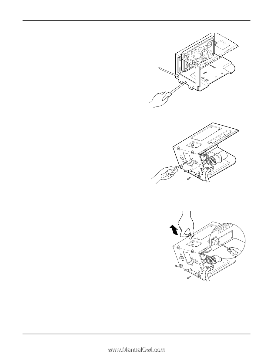
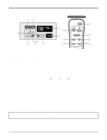
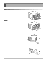
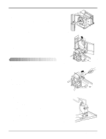
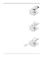
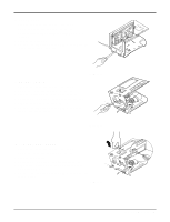
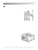
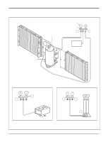
13. THERMISTOR 1. Remove the control box. (Refer to section 3) 2. Unfold the control box. (Refer to section 10) 3. Disconnect the thermistor terminals from main P.W.B assembly. 4. Remove the thermistor. 5. Re-install the components by referring to the removal pro- cedure above. (See Figure 30) 14. ROTARY SWITCH 1. Remove the control box. (Refer to section 3) 2. Unfold the control box. (Refer to section 10) 3. Remove 2 screws which fasten the rotary switch. 4. Disconnect all the leads of the rotary switch terminals. 5. Remove the rotary switch. (See Fig. 31) 6. Re-install the components by referring to the above removal procedure, above. Figure 30 Figure 31 15. SYNCHRONOUS MOTOR 1. Remove the control box. (Refer to section 3) 2. Unfold the control box. (Refer to section 10) 3. Remove the crankshaft. 4. Disconnect all the leads of the synchronous motor. 5. Remove the 2 screws which fasten the synchronous motor. (See Fig. 32) 6. Re-install the components by referring to the removal pro- cedure, above. Figure 32 Disassembly Service Manual 17
-
 1
1 -
2
-
3
-
4
-
5
-
6
-
7
-
8
-
9
-
10
-
11
-
 12
12 -
 13
13 -
 14
14 -
 15
15 -
 16
16 -
 17
17 -
 18
18 -
 19
19 -
 20
20 -
 21
21 -
 22
22 -
23
-
24
-
25
-
26
-
27
-
28
-
29
-
30
-
31
-
32
-
33
-
34
-
35
-
36
 |
 |