LG PQCPB11A0E Owner's Manual - Page 27
Note: PCB part number, Caution: Setting the PI485 DIP switch
 |
View all LG PQCPB11A0E manuals
Add to My Manuals
Save this manual to your list of manuals |
Page 27 highlights
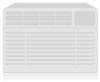
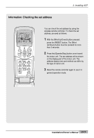
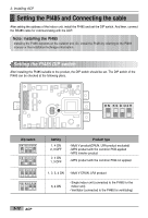
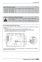
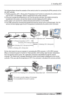
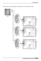
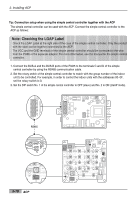
2. Installing ACP Note: PCB part number The MPS product with the common PCB applied has the following PCB part number: • PCB P/NO. : 6871A20910A ~ Z • PCB P/NO. : 6871A20917A ~ Z • PCB P/NO. : 6871A20918A ~ Z Caution: Setting the PI485 DIP switch If the air conditioner selection switch is incorrectly set, the air conditioner may incorrectly operate. For more information about installing the PI485, see the PI485(M) manual. Tip: Checking the PI485 DIP switch setting It can be checked whether the indoor unit address and the DIP switch of the PI485 are correctly set as follows: • The LED01G blinks as many as the number of the connected indoor units. • The LED02G and the LED03G continue to blink alternately. (When the LRA/CRUN is connected, the LED02G may blink more than the LED03G.) LED03G LED02G LED01G If the LED is abnormally different from the above description, check again the indoor unit address setting and the DIP switch setting. Installation/Owner's Manual 2-13 ON KS D O4H ON KSDO4H L1 2 3 4
-
 1
1 -
2
-
3
-
4
-
5
-
6
-
7
-
8
-
9
-
10
-
11
-
12
-
13
-
14
-
15
-
16
-
17
-
18
-
19
-
20
-
21
-
 22
22 -
 23
23 -
 24
24 -
 25
25 -
 26
26 -
 27
27 -
 28
28 -
 29
29 -
 30
30 -
 31
31 -
 32
32 -
33
-
34
-
35
-
36
-
37
-
38
-
39
-
40
-
41
-
42
-
43
-
44
-
45
-
46
-
47
-
48
-
49
-
50
-
51
-
52
-
53
-
54
-
55
-
56
-
57
-
58
-
59
-
60
-
61
-
62
-
63
-
64
-
65
-
66
-
67
-
68
-
69
-
70
-
71
-
72
-
73
-
74
-
75
-
76
-
77
-
78
-
79
-
80
-
81
-
82
-
83
-
84
-
85
-
86
-
87
-
88
-
89
-
90
-
91
-
92
-
93
-
94
-
95
-
96
-
97
-
98
-
99
-
100
-
101
-
102
-
103
-
104
-
105
-
106
-
107
-
108
-
109
-
110
-
111
-
112
-
113
-
114
-
115
-
116
-
117
-
118
-
119
-
120
-
121
-
122
-
123
-
124
-
125
-
126
-
127
-
128
-
129
-
130
-
131
-
132
-
133
-
134
-
135
-
136
-
137
-
138
-
139
-
140
-
141
-
142
-
143
-
144
-
145
-
146
-
147
-
148
-
149
-
150
-
151
-
152
-
153
-
154
-
155
-
156
-
157
-
158
-
159
-
160
-
161
-
162
-
163
 |
 |