LG RAD-123A Owners Manual - Page 16
Do Not Drill A Hole In The, Bottom Pan.
 |
View all LG RAD-123A manuals
Add to My Manuals
Save this manual to your list of manuals |
Page 16 highlights
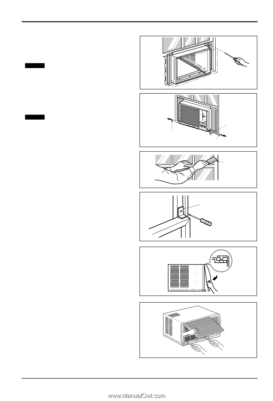
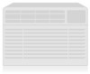
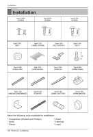
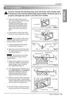
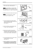
Installation 9. Attach each Frame Curtain the window sash using screws (Type C).(See Figure 6) Tip! : DO NOT DRILL A HOLE IN THE BOTTOM PAN. The unit is designed to operate with approximately 1/2" of water in bottom pan. 10. Slide the unit into the cabinet.(See Figure 7) Tip! : For security purpose, reinstall screws(Type A) at cabinet's sides. 11. Cut the Foam-Strip to the proper length and insert between the upper window sash and the lower window sash. (See Figure 8) 12. Attach the Window Locking Bracket with a Type C screw. (See Figure 9) 13. Attach the front grille to the cabinet by inserting the tabs on the grille into the tabs on the front of the cabinet. Push the grille in until it snaps into place. (See Figure 10) Type C Figure 6 Screw(Type A) Power Cord Screw(Type A) Figure 7 Foam-Strip Figure 8 Window Locking Bracket Figure 9 14. Lift the inlet grille and secure it with a Type A screw through the front grille. (See Figure 11) 15. Window installation of room air conditioner is now completed. See ELECTRICAL DATA for attaching power cord to electrical outlet. Figure 10 Figure 11 16 Room Air Conditioner
-
 1
1 -
2
-
3
-
4
-
5
-
6
-
7
-
8
-
9
-
10
-
 11
11 -
 12
12 -
 13
13 -
 14
14 -
 15
15 -
 16
16 -
 17
17 -
 18
18 -
 19
19 -
 20
20 -
 21
21 -
22
-
23
-
24
-
25
-
26
-
27
-
28
-
29
-
30
-
31
-
32
-
33
-
34
-
35
-
36
-
37
-
38
-
39
-
40
-
41
-
42
-
43
-
44
-
45
-
46
-
47
-
48
-
49
-
50
 |
 |