LG T710BH Service Manual - Page 10
Image Rotation Tilt Circuit., Video Pre-Amp Circuit., Video Output Amp Circuit. - 17
 |
View all LG T710BH manuals
Add to My Manuals
Save this manual to your list of manuals |
Page 10 highlights
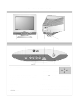
15. Image Rotation (Tilt) Circuit. This circuit corrects the tilt of the screen by supplying the image rotation signal to the tilt coil which is attached near the deflection yoke of the CRT. 17. Video Output Amp Circuit. This circuit amplifies the video signal which comes from the video pre-amp circuit and amplified it to applied the CRT cathode. 16. Video Pre-Amp Circuit. This circuit amplifies the analog video signal from 0-0.7V to 0-4V. It is operated by taking the clamp, R, G, B drive and contrast signal from the Micom(IC401). - 10 -
-
 1
1 -
2
-
3
-
4
-
 5
5 -
 6
6 -
 7
7 -
 8
8 -
 9
9 -
 10
10 -
 11
11 -
 12
12 -
 13
13 -
 14
14 -
 15
15 -
16
-
17
-
18
-
19
-
20
-
21
-
22
-
23
-
24
-
25
-
26
-
27
-
28
-
29
-
30
-
31
-
32
-
33
-
34
-
35
-
36
-
37
 |
 |

- 10 -
15. Image Rotation (Tilt) Circuit.
This circuit corrects the tilt of the screen by supplying the
image rotation signal to the tilt coil which is attached near
the deflection yoke of the CRT.
16. Video Pre-Amp Circuit.
This circuit amplifies the analog video signal from 0-0.7V
to 0-4V. It is operated by taking the clamp, R, G, B drive
and contrast signal from the Micom(IC401).
17. Video Output Amp Circuit.
This circuit amplifies the video signal which comes from
the video pre-amp circuit and amplified it to applied the
CRT cathode.