Lasko 2505 User Manual - Page 4
Model 2505, Modelo 2505
 |
View all Lasko 2505 manuals
Add to My Manuals
Save this manual to your list of manuals |
Page 4 highlights
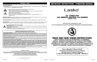
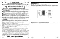
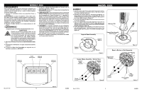
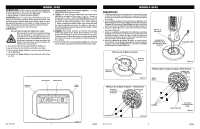
MODEL 2505 OPERATION This Fan may be operated by the Manual Controls located on top of the unit (as shown in Figure 5) or by the Remote Control (shown in Figure 6). 1. Place the Fan on a firm and level surface. CAUTION: Plastic or rubber tabs, like the feet on this unit, may stick to furniture surfaces and/or hardwood floors. The unit may leave a residue that could darken, stain or leave permanent blemishes on the finish of certain furniture surfaces, including wood surfaces, and/or hardwood floors. 2. Plug the cord set into a 120 volt outlet. WARNING Be sure that the plug fits tightly into outlet. When plugs fit loosely into receptacles, they may slip partially or completely out of the receptacle with only the slight movement of the attached cord. Receptacles in this condition may overheat and pose a serious fire hazard; if covered by a curtain or drape, the fire hazard is even greater. 7. OSCILLATION: Press the Oscillation Button ( ) to start and stop the oscillation function. 8. TIMER: The timer function allows the unit to be set to operate for a length of time from 1 hour to 7 hours, in increments of 1 hour. Press the Timer Button ( ) to set the length of time desired. Each time the timer button is pressed, the time is increased by 1 hour. After reaching 7 hours, pressing the timer button once more will reset the Fan to continuous running. The lights on the front of the unit will light up appropriately with the length of time that the Fan is set for. 9. IONIZER: The ionizer function on this Fan will operate within any speed mode. Press the Ion Button ( ) once to turn this function on and a second time to turn it off. The Fan must be ON for the ionizer to be functional. When the ionizer is turned on it will assist in the purification of the room air. 10.To turn the Fan OFF, press the Power Button ( ) until unit turns off then unplug the unit from the electrical outlet. 3. Turn the Fan ON by pressing the Power Button ( ). 4. Upon turning the Fan ON, the unit will be on HIGH. 5. Pressing the Power Button a second time will set the Fan to MEDIUM. 6. Pressing the Power Button a third time will set the Fan to LOW. MODELO 2505 ENSAMBLADO 1. Cuidadosamente retire el ventilador de la bolsa plástica y de la caja. Para facilidad de ensamblado, coloque el ventilador en forma horizontal para que la parrilla frontal esté apuntando hacia abajo. 2. Arme las Bases de Apoyo interconectando las Salientes en la Base de Apoyo A dentro de los Orificios de Salientes en la Base de Apoyo B. Introduzca el Cable Eléctrico a través del orificio grande en el centro de la Montura de la Base de Apoyo. (Figura 1) 3. Asegure los (4) Tornillos en los cuatro orificios de la parte inferior de la base. (Figura 2) 4. Alinee las Lengüetas de Alineación de la Montura de la Base de Apoyo con las ranuras de alineación en la parte inferior del ventilador, teniendo cuidado de que el canal del cable en la parte inferior de la base de apoyo debe estar apuntando hacia la parte posterior del ventilador. (Figura 3) 5. Asegure la Montura de la Base de Apoyo a la parte inferior del ventilador con (4) Tornillos de Largo. Suavemente elimine cualquier sobrante del Cable Eléctrico y colóquelo en el Orificio de Colocación del Cable. (Figura 4) Ranura de Alineación Lengüeta de Alineación de la Montura de la Base de Apoyo Montura de la Base de Apoyo Base de Apoyo A Canal del Cable Figura 3 Oscillation Button Timer Button Ionizer Button Power Button Base de Apoyo B Salientes Figura 1 Montura de la Unidad de base a Parte Inferior Montura de la Base de Apoyo Montura de la Base de Apoyo - Vista Inferior Montura de la Base de Apoyo Rev. G 11/15 Tornillos Figure 5 4 2505ES Rev. G 11/15 Tornillos Figura 2 9 Orificio de Colocación del Cable Cable Eléctrico Figura 4 2505ES
-
 1
1 -
 2
2 -
 3
3 -
 4
4 -
 5
5 -
 6
6
 |
 |
