Lenovo 28479WU Hardware Maintenance Manual - Page 91
PCI Express Mini Card for wireless LAN on I/O Controller Hub ICH
 |
View all Lenovo 28479WU manuals
Add to My Manuals
Save this manual to your list of manuals |
Page 91 highlights
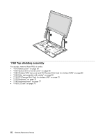
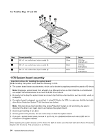
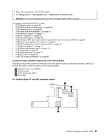
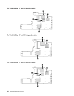
1. Place the computer on a horizontal surface. 2. Run Diagnostics ➙ ThinkPad Devices ➙ HDD Active Protection Test. Attention: Do not apply physical shock to the computer while the test is running. For access, remove these FRUs, in order: • "1010 Battery pack" on page 58 • "1020 Optical drive or travel cover" on page 58 • "1030 Thermal cover" on page 59 • "1040 Hard disk drive assembly" on page 60 • "1050 Memory module" on page 61 • "1060 Fan assembly" on page 62 • "1070 Microprocessor" on page 65 • "1080 Wireless WAN slot cover and PCI Express Mini Card for wireless WAN" on page 66 • "1090 Palm rest assembly with cables" on page 69 • "1100 PCI Express Mini Card for wireless LAN" on page 72 • "1110 Backup battery" on page 74 • "1120 Bluetooth daughter card" on page 74 • "1130 Keyboard" on page 75 • "1140 Keyboard bezel" on page 77 • "1150 LCD unit" on page 79 • "1160 Top shielding assembly" on page 82 Location of major sensitive components on the system board Following components soldered on the top side of the system board are extremely sensitive. When you service the system board, avoid any kind of rough handling. a Integrated video chip (GMCH) b Microprocessor c I/O Controller Hub (ICH ) d Video chip For ThinkPad Edge 14" and E40 integrated models: a b c Chapter 8. Removing or replacing a FRU 85
-
 1
1 -
2
-
3
-
4
-
5
-
6
-
7
-
8
-
9
-
10
-
11
-
12
-
13
-
14
-
15
-
16
-
17
-
18
-
19
-
20
-
21
-
22
-
23
-
24
-
25
-
26
-
27
-
28
-
29
-
30
-
31
-
32
-
33
-
34
-
35
-
36
-
37
-
38
-
39
-
40
-
41
-
42
-
43
-
44
-
45
-
46
-
47
-
48
-
49
-
50
-
51
-
52
-
53
-
54
-
55
-
56
-
57
-
58
-
59
-
60
-
61
-
62
-
63
-
64
-
65
-
66
-
67
-
68
-
69
-
70
-
71
-
72
-
73
-
74
-
75
-
76
-
77
-
78
-
79
-
80
-
81
-
82
-
83
-
84
-
85
-
 86
86 -
 87
87 -
 88
88 -
 89
89 -
 90
90 -
 91
91 -
 92
92 -
 93
93 -
 94
94 -
 95
95 -
 96
96 -
97
-
98
-
99
-
100
-
101
-
102
-
103
-
104
-
105
-
106
-
107
-
108
-
109
-
110
-
111
-
112
-
113
-
114
-
115
-
116
-
117
-
118
-
119
-
120
-
121
-
122
-
123
-
124
-
125
-
126
-
127
-
128
-
129
-
130
-
131
-
132
-
133
-
134
-
135
-
136
-
137
-
138
-
139
-
140
-
141
-
142
-
143
-
144
-
145
-
146
-
147
-
148
-
149
-
150
-
151
-
152
-
153
-
154
-
155
-
156
-
157
-
158
 |
 |
