Lenovo 438923U User Manual
Lenovo 438923U Manual
 |
View all Lenovo 438923U manuals
Add to My Manuals
Save this manual to your list of manuals |
Lenovo 438923U manual content summary:
- Lenovo 438923U | User Manual - Page 1
ThinkPad T510, T510i, and W510 Hardware Maintenance Manual - Lenovo 438923U | User Manual - Page 2
- Lenovo 438923U | User Manual - Page 3
ThinkPad T510, T510i, and W510 Hardware Maintenance Manual - Lenovo 438923U | User Manual - Page 4
Note Before using this information and the product it supports, be sure to read the general information under "Notices" on page 201. First Edition (December 2009) © Copyright Lenovo 2009. LENOVO products, data, computer software, and services have been developed exclusively at private expense and - Lenovo 438923U | User Manual - Page 5
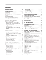
manual v Safety information 1 General safety 2 Electrical safety 3 Safety inspection guide Lenovo 2009 Beep symptoms 67 No-beep symptoms 67 LCD-related symptoms 68 Intermittent problems 69 Undetermined problems 69 Installing and configuring RAID . . . . 71 Supported servicing ThinkPad - Lenovo 438923U | User Manual - Page 6
Premium (32 bit) DVDs . . 194 Windows 7 Home Premium (64 bit) DVDs . . 195 Windows 7 Professional (32 bit) DVDs . . . . 196 Windows 7 Professional (64 bit) DVDs . . . . 198 Common service tools 200 Notices 201 Trademarks 202 iv ThinkPad T510, T510i, and W510 Hardware Maintenance Manual - Lenovo 438923U | User Manual - Page 7
with ThinkPad products. Use this manual along with the advanced diagnostic tests to troubleshoot problems effectively. Before servicing a ThinkPad product, be sure to read all the information under "Safety information" on page 1 and "Important service information" on page 39. © Copyright Lenovo - Lenovo 438923U | User Manual - Page 8
vi ThinkPad T510, T510i, and W510 Hardware Maintenance Manual - Lenovo 438923U | User Manual - Page 9
presents following safety information that you need to be familiar with before you service a ThinkPad Notebook. v "General safety" on page 2 v "Electrical safety" on page 3 v "Safety inspection guide" on page 5 v "Handling devices that are sensitive to electrostatic discharge" on page 6 v "Grounding - Lenovo 438923U | User Manual - Page 10
v Place removed covers and other parts in a safe place, away from all personnel, while you are servicing the machine. v Keep your toolcase away from walk areas so that other people will not trip over or cover them with labels or stickers. 2 ThinkPad T510, T510i, and W510 Hardware Maintenance Manual - Lenovo 438923U | User Manual - Page 11
the room emergency power-off (EPO) switch, disconnecting switch, or electrical outlet. If an electrical accident occurs, you can then operate the switch or unplug safety precautions when you work with very high voltages; Instructions for these precautions are in the safety sections of maintenance - Lenovo 438923U | User Manual - Page 12
is conductive; such touching can cause personal injury and machine damage. v Do not service the following parts with the power on when they are removed from their normal operating Switch off power. - Send another person to get medical aid. 4 ThinkPad T510, T510i, and W510 Hardware Maintenance Manual - Lenovo 438923U | User Manual - Page 13
ThinkPad features or options not covered by this inspection guide . If any unsafe conditions are present, you must determine how serious the apparent hazard could be and whether you can continue without first correcting the problem every service task Power off the computer. Disconnect the power - Lenovo 438923U | User Manual - Page 14
specific service computers. Grounding requirements Electrical grounding of the computer is required for operator safety and correct system function. Proper grounding of the electrical outlet can be verified by a certified electrician. 6 ThinkPad T510, T510i, and W510 Hardware Maintenance Manual - Lenovo 438923U | User Manual - Page 15
Safety notices (multilingual translations) The safety notices in this section are provided in the following languages: v English v Arabic v Brazilian Portuguese v French v German v Hebrew v Japanese v Korean v Spanish v Traditional Chinese Safety information 7 - Lenovo 438923U | User Manual - Page 16
other small parts are in place and are not left loose inside the computer. Verify this by shaking the computer and listening for rattling sounds. Metallic parts or metal flakes can cause symptoms from the fluid are present after washing. 8 ThinkPad T510, T510i, and W510 Hardware Maintenance Manual - Lenovo 438923U | User Manual - Page 17
burn personnel or combustible materials. DANGER Unless hot swap is allowed for the FRU being replaced, do as follows before removing it: power off the computer, unplug all power cords from electrical outlets, remove the battery pack, and disconnect any interconnecting cables. Safety information 9 - Lenovo 438923U | User Manual - Page 18
10 ThinkPad T510, T510i, and W510 Hardware Maintenance Manual - Lenovo 438923U | User Manual - Page 19
Safety information 11 - Lenovo 438923U | User Manual - Page 20
, lave as áreas afetadas imediatamente com água durante pelo menos 15 minutos. Procure cuidados médicos se algum sintoma causado pelo fluido surgir após a lavagem. 12 ThinkPad T510, T510i, and W510 Hardware Maintenance Manual - Lenovo 438923U | User Manual - Page 21
PERIGO Para evitar choque elétrico, não remova a capa plástica que protege a parte inferior da placa inversora. PERIGO Embora as principais baterias possuam baixa voltagem, uma bateria em curto-circuito ou aterrada pode produzir corrente o bastante para queimar materiais de pessoal ou inflamáveis. - Lenovo 438923U | User Manual - Page 22
mains une partie du fluide, rincez-les abondamment pendant au moins quinze minutes. Consultez un médecin si des symptômes persistent après le lavage. 14 ThinkPad T510, T510i, and W510 Hardware Maintenance Manual - Lenovo 438923U | User Manual - Page 23
DANGER Afin d'éviter tout risque de choc électrique, ne retirez pas le cache en plastique protégeant la partie inférieure de la carte d'alimentation. DANGER Bien que le voltage des batteries principales soit peu élevé, le court-circuit ou la mise à la masse d'une batterie peut produire suffisamment - Lenovo 438923U | User Manual - Page 24
Schrauben, Federn oder andere Kleinteile fehlen oder im Gehäuse vergessen wurden. Der Computer muß geschüttelt und auf Klappergeräusche geprüft werden. Metallteile oder-splitter falscher Batterien kann zu Entzündung oder Explosion führen. 16 ThinkPad T510, T510i, and W510 Hardware Maintenance Manual - Lenovo 438923U | User Manual - Page 25
Entsorgung die örtlichen Bestimmungen für Sondermüll beachten. Der LCD-Bildschirm besteht aus Glas und kann zerbrechen, wenn er unsachgemäß behandelt wird oder der Computer auf den Boden fällt. Wenn der Bildschirm beschädigt ist und die darin befindliche Flüssigkeit in Kontakt mit Haut und Augen ger - Lenovo 438923U | User Manual - Page 26
18 ThinkPad T510, T510i, and W510 Hardware Maintenance Manual - Lenovo 438923U | User Manual - Page 27
Safety information 19 - Lenovo 438923U | User Manual - Page 28
20 ThinkPad T510, T510i, and W510 Hardware Maintenance Manual - Lenovo 438923U | User Manual - Page 29
Safety information 21 - Lenovo 438923U | User Manual - Page 30
22 ThinkPad T510, T510i, and W510 Hardware Maintenance Manual - Lenovo 438923U | User Manual - Page 31
Safety information 23 - Lenovo 438923U | User Manual - Page 32
inmediatamente las áreas afectadas con agua durante 15 minutos como mínimo. Obtenga atención medica si se presenta algún síntoma del fluido despues de lavarse. 24 ThinkPad T510, T510i, and W510 Hardware Maintenance Manual - Lenovo 438923U | User Manual - Page 33
PELIGRO Para evitar descargas, no quite la cubierta de plástico que rodea la parte baja de la tarjeta invertida. PELIGRO Aunque las baterías principales tienen un voltaje bajo, una batería cortocircuitada o con contacto a tierra puede producir la corriente suficiente como para quemar material - Lenovo 438923U | User Manual - Page 34
26 ThinkPad T510, T510i, and W510 Hardware Maintenance Manual - Lenovo 438923U | User Manual - Page 35
Safety information 27 - Lenovo 438923U | User Manual - Page 36
, or any other optical storage device could result in exposure to hazardous laser radiation. There are no serviceable parts inside those drives. Do not open. A CD-ROM drive, a DVD-ROM drive, or any , and avoid direct exposure to the beam. 28 ThinkPad T510, T510i, and W510 Hardware Maintenance Manual - Lenovo 438923U | User Manual - Page 37
Safety information 29 - Lenovo 438923U | User Manual - Page 38
certificada nos Estados Unidos em conformidade com os requisitos do Department of Health and Human Services 21 Code of Federal Regulations (DHHS 21 CFR), Subcapítulo J, para produtos a óticos, e evite exposição direta ao feixe. 30 ThinkPad T510, T510i, and W510 Hardware Maintenance Manual - Lenovo 438923U | User Manual - Page 39
Certains modèles d'ordinateur ThinkPad sont équipés d'origine d'une unité de stockage optique telle qu'une unité de CD-ROM ou de DVD-ROM. Ces unités sont également vendues séparé - Lenovo 438923U | User Manual - Page 40
Einige ThinkPad-Modelle sind werkseitig mit einem CD-ROM- oder DVD-ROM-Laufwerk ausgestattet. CD- und DVD-Laufwerke kö Laserstrahlung, wenn geöfnet. Nicht in den Strahl blicken. Keine Lupen oder Spiegel verwenden. Strahlungsbereich meiden. 32 ThinkPad T510, T510i, and W510 Hardware Maintenance Manual - Lenovo 438923U | User Manual - Page 41
Safety information 33 - Lenovo 438923U | User Manual - Page 42
34 ThinkPad T510, T510i, and W510 Hardware Maintenance Manual - Lenovo 438923U | User Manual - Page 43
Safety information 35 - Lenovo 438923U | User Manual - Page 44
se certifica que en los Estados Unidos cumple los requisitos del Department of Health and Human Services 21 Code of Federal Regulations (DHHS 21 CFR) Subchapter J para productos láser de Clase pticos y evite la exposición directa al rayo. 36 ThinkPad T510, T510i, and W510 Hardware Maintenance Manual - Lenovo 438923U | User Manual - Page 45
Safety information 37 - Lenovo 438923U | User Manual - Page 46
38 ThinkPad T510, T510i, and W510 Hardware Maintenance Manual - Lenovo 438923U | User Manual - Page 47
in this manual. After a system board is replaced, ensure that the latest BIOS is loaded to the system board before completing the service action. To download software fixes, drivers, and BIOS, do as follows: 1. Go to http://www.lenovo.com/support 2. Enter the product number of the computer or press - Lenovo 438923U | User Manual - Page 48
and servicing FRUs: v If you are instructed to replace a FRU but the replacement does not correct the problem, reinstall the original FRU before you continue. v Some computers have Symptom-to-FRU Index for the computer you are servicing. 40 ThinkPad T510, T510i, and W510 Hardware Maintenance Manual - Lenovo 438923U | User Manual - Page 49
configure an IBM® or a Lenovo solution from an eSite, and that has been negotiated between IBM or Lenovo and the customer. A unique 4-digit identify which FRUs are used to support CTO, CMV, and GAV products the following Web site: http://www.lenovo.com/support/site.wss/document.do?lndocid=LOOK- - Lenovo 438923U | User Manual - Page 50
be accessed at the following Web site: http://www.lenovo.com/ support v To view the key commodities, click on PARTS INFORMATION select SERVICE PARTS. Under "Parts Information by Date" select SYSTEM SERVICE PARTS. The list of service parts ThinkPad T510, T510i, and W510 Hardware Maintenance Manual - Lenovo 438923U | User Manual - Page 51
ThinkPad model that supports the PC-Doctor® for DOS diagnostics program. Some descriptions might not apply to your particular computer. Before you go to the checkout guide, be sure to read the following important notes. Important notes: v Only certified trained personnel should service the computer - Lenovo 438923U | User Manual - Page 52
computer password (making the computer unusable) v Sticky keys caused by spilling a liquid onto the keyboard v Use of an incorrect ac adapter on laptop products The following symptoms might indicate damage caused by nonwarranted activities: v Missing parts might be a symptom of unauthorized service - Lenovo 438923U | User Manual - Page 53
following Web site: http:// www.lenovo.com/support To create the PC-Doctor diagnostic CD, follow the instructions on the Web site. For some possible configurations of the computer, PC-Doctor might not run correctly. To avoid this problem, you need to initialize the computer setup by use of the BIOS - Lenovo 438923U | User Manual - Page 54
only the internal optical drive of the ThinkPad Notebook. To run the test, do as follows: 1. Turn off the computer. 2. Make sure that the internal optical drive that is supported as a startup device is attached to the computer. 3. Turn on the computer. If the computer cannot be powered on, go to - Lenovo 438923U | User Manual - Page 55
ThinkPad Notebook. If you have an external monitor attached to your computer, detach it before running PC-Doctor for DOS. v To test Digital Signature Chip, the security chip must be set to Active. 10. Run the applicable function test. 11. Follow the instructions on the screen. If there is a problem - Lenovo 438923U | User Manual - Page 56
System Toolbox) is available at the following Web site: http://www.lenovo.com/support To install the latest Lenovo ThinkVantage Toolbox (Lenovo System Toolbox) on the computer, follow the instructions on the Web site. To run this program, do as follows: Windows 7: While the Windows operating system - Lenovo 438923U | User Manual - Page 57
2. Diagnostics --> Systemboard 3. If the docking station or the port replicator is attached to the ThinkPad Notebook, detach it. 4. Place the computer on a horizontal surface, and run Diagnostics --> ThinkPad Devices --> HDD Active Protection Test. Note: Do not apply any physical shock to the - Lenovo 438923U | User Manual - Page 58
hardware problem. If the pointer stops after a short time, no service action is necessary. Touch Pad If enabling the TrackPoint does not correct the problem, the problem, continue with the following: v Interactive Tests --> Mouse 50 ThinkPad T510, T510i, and W510 Hardware Maintenance Manual - Lenovo 438923U | User Manual - Page 59
pack supplies power when you turn on the computer. If you suspect a power problem, see the appropriate one of the following power Output voltage of pin no.2 of the ac adapter may different from the one you are servicing. 3. If the voltage is not correct, replace the ac adapter. 4. If the voltage - Lenovo 438923U | User Manual - Page 60
If the battery pack becomes hot, it may not be able to charge. Remove it from the computer and leave it at room temperature for a while. After it cools down, reinstall and recharge it. the resistance is correct, replace the system board. 52 ThinkPad T510, T510i, and W510 Hardware Maintenance Manual - Lenovo 438923U | User Manual - Page 61
Checking the backup battery Do the following: 1. Power off the computer, and unplug the ac adapter from it. 2. Turn the computer upside down. 3. Remove the battery pack (see "1010 Battery pack" on page 87). 4. Remove the backup battery (see "1120 Backup battery" on page 107). 5. Measure - Lenovo 438923U | User Manual - Page 62
54 ThinkPad T510, T510i, and W510 Hardware Maintenance Manual - Lenovo 438923U | User Manual - Page 63
62 Service Web site: When the latest maintenance diskette and the system program service diskette become available, they will be posted on http://www.lenovo.com disc set consists of the user instructions and the following set of DVDs to restore the computer to the original factory configuration. - Lenovo 438923U | User Manual - Page 64
instructions on the screen. 6. Click Yes in the displayed window to begin the operating system recovery process. 7. Insert the Applications and Drivers the computer is turned on. The computer does not start until the password is entered. 56 ThinkPad T510, T510i, and W510 Hardware Maintenance Manual - Lenovo 438923U | User Manual - Page 65
set. If it has, it can be used for access to the hard disk drive. If no master HDP is available, neither Lenovo nor Lenovo authorized service technicians provide any services to reset either the user or the master HDP, or to recover data from the hard disk drive. The hard disk drive can - Lenovo 438923U | User Manual - Page 66
service technician: 1. Turn on the computer. 2. When the ThinkPad logo comes up, immediately press F1 to enter BIOS Setup Utility. For models supporting be made available to the service technician, neither Lenovo nor Lenovo authorized service technicians provide any services to reset the user HDPs - Lenovo 438923U | User Manual - Page 67
7. Type the current master HDP in the Enter Current Password field. then leave the Enter New Password field blank, and press Enter twice. 8. Press F10. 9. Select Yes in the Setup Configuration window. Both user HDP and master HDP will have been removed. Related service information 59 - Lenovo 438923U | User Manual - Page 68
computer computer computer is a Windows 7 model, it does not support ThinkVantage Productivity Center. To end screen blank mode and resume normal operation, press any key. Sleep (standby) mode When the computer computer computer enters the power-saving mode automatically. To cause the computer - Lenovo 438923U | User Manual - Page 69
timer elapses. Note: The computer does not accept any input off. Note: If the computer enters the hibernation mode while system. To cause the computer to enter hibernation mode, +F4 keys. Also, the computer goes into hibernation mode automatically turned on, the computer returns from hibernation - Lenovo 438923U | User Manual - Page 70
the problem, put the original part back in the computer. Do not replace a nondefective FRU. This index can also help you determine, during regular servicing, what "Intermittent problems" on page 69. Note: For a device not supported by diagnostic codes in the ThinkPad Notebooks, see the manual for - Lenovo 438923U | User Manual - Page 71
for more than 8 hours by connecting the ac adapter. 2. Replace the backup battery and run BIOS Setup Utility to reset the time and date. Related service information 63 - Lenovo 438923U | User Manual - Page 72
System board. 0271 Date and time error-Neither the date nor the time is set in the computer. Run BIOS Setup Utility to reset the time and date. 0280 Previous boot incomplete- Default card that you installed. 2. System board. 64 ThinkPad T510, T510i, and W510 Hardware Maintenance Manual - Lenovo 438923U | User Manual - Page 73
computer. 3. Run Diagnostics --> ThinkPad Devices --> HDD Active Protection Test. 2010 Warning: Your internal hard disk drive (HDD) may not function correctly on this system. Ensure that your HDD is supported at http://www.lenovo.com/support 2100 Initialization error service information 65 - Lenovo 438923U | User Manual - Page 74
Backup battery. 3. System board. 1. Restore the system configuration to what it was before the computer entered hibernation mode. 2. If memory size has been changed, re-create the hibernation file. and add the device in boot order. 66 ThinkPad T510, T510i, and W510 Hardware Maintenance Manual - Lenovo 438923U | User Manual - Page 75
set. Type the password and press Enter. The hard-disk password prompt appears. A hard-disk password is set. Type the password and press Enter. Related service information 67 - Lenovo 438923U | User Manual - Page 76
LCD for the notebook computer contains many thin-film transistors (TFTs). The presence of a small number of dots that are missing, discolored, or always lighted is characteristic of TFT LCD technology, but excessive pixel problems can cause viewing concerns. If the LCD you are servicing has two or - Lenovo 438923U | User Manual - Page 77
operating, follow these procedures to isolate the failing FRU (do not isolate FRUs that have no defects). Verify that all attached devices are supported by the computer. Verify that the power supply being used at the time of the failure is operating correctly. (See "Power system checkout" on page 51 - Lenovo 438923U | User Manual - Page 78
70 ThinkPad T510, T510i, and W510 Hardware Maintenance Manual - Lenovo 438923U | User Manual - Page 79
make sure of the current RAID setting on the computer you are servicing. This product supports either RAID Level 0 (RAID 0) or RAID Level Deleting RAID volumes" on page 72 Supported RAID configurations The following RAID configurations are supported on ThinkPad W510: RAID Level 0 (RAID Lenovo 2009 71 - Lenovo 438923U | User Manual - Page 80
press Enter. Attention: If the Serial ATA item in the BIOS Setup Utility menu of the computer you are servicing was set to AHCI when it was manufactured, then to create a RAID array you must more information, see "Creating RAID volumes." 72 ThinkPad T510, T510i, and W510 Hardware Maintenance Manual - Lenovo 438923U | User Manual - Page 81
Status indicators This chapter presents the system status indicators that show the status of the computer. 1 2 3 4 5 6 9 8 7 12 11 10 © Copyright Lenovo 2009 73 - Lenovo 438923U | User Manual - Page 82
Ultrabay Enhanced device. When this indicator is on, do not put the computer into sleep (standby) mode or turn off the computer. Note: Do not move the system while the green device access light device is ready to be attached or detached. 74 ThinkPad T510, T510i, and W510 Hardware Maintenance Manual - Lenovo 438923U | User Manual - Page 83
mode. Quick blinking orange: An error has been occurred in the battery. The battery status indicator is off: The battery pack of the computer is detached. 12 Color sensor status Green: Calibration is complete. When the lid is opened, the indicator turns off. Blinking green: Display colors - Lenovo 438923U | User Manual - Page 84
76 ThinkPad T510, T510i, and W510 Hardware Maintenance Manual - Lenovo 438923U | User Manual - Page 85
this combination, a panel for selecting a power plan (power scheme) appears. Fn+F4 Notes: To use this combination of the keys, ThinkPad PM device driver must have been installed on the computer. If you have logged on with an administrator user ID in Windows XP, and you press Fn+F3, the panel for - Lenovo 438923U | User Manual - Page 86
Director, and change the settings. Note: If the computer is an Windows 7 model, it does not support presentation schemes, however the Fn+F7 combination might still be of the UltraNav® pointing device. Reserved. Reserved. Reserved. 78 ThinkPad T510, T510i, and W510 Hardware Maintenance Manual - Lenovo 438923U | User Manual - Page 87
seconds. Fn+PgUp Fn+Home Notes: To use this combination of the keys, ThinkPad PM device driver must have been installed on the computer. Though the screen fades out immediately after Fn+F12 are pressed, the computer does not enter the hibernation mode immediately. Do not move the system until the - Lenovo 438923U | User Manual - Page 88
80 ThinkPad T510, T510i, and W510 Hardware Maintenance Manual - Lenovo 438923U | User Manual - Page 89
Screw notices Loose screws can cause a reliability problem. In the ThinkPad Notebook, this problem is addressed with special nylon-coated screws that have are tightened firmly. v Ensure torque screw drivers are calibrated correctly following country specifications. © Copyright Lenovo 2009 81 - Lenovo 438923U | User Manual - Page 90
number by doing the following: 1. Install the LENOVO ThinkPad Hardware Maintenance Diskette Version 1.76 or later and restart the computer. 2. From the main menu, select 1. Set System Identification. 3. Select 1. Add S/N data from EEPROM. Follow the instructions on the screen. If the MTM and Product - Lenovo 438923U | User Manual - Page 91
or later. 1. Insert the LENOVO ThinkPad Hardware Maintenance Diskette Version 1.76 or later, and restart the computer. 2. From the main menu, select 6. Set ECA Information. 3. To read ECA information, select 2. Read ECA/rework number from EEPROM and follow the instruction. 4. To read box build date - Lenovo 438923U | User Manual - Page 92
84 ThinkPad T510, T510i, and W510 Hardware Maintenance Manual - Lenovo 438923U | User Manual - Page 93
observe the following general rules: 1. Do not try to service any computer unless you have been trained and certified. An untrained person Before removing any FRU, turn off the computer, unplug all power cords from electrical outlets, remove the battery pack, and then Copyright Lenovo 2009 85 - Lenovo 438923U | User Manual - Page 94
Table 9. Removal steps of SIM card Some models of the ThinkPad T510, T510i, and W510 you are servicing might have the SIM card that the customer has installed. If the computer you are servicing has the SIM card, remove it before you start the servicing. To remove the SIM card, you need to remove the - Lenovo 438923U | User Manual - Page 95
if the battery pack is physically damaged or a customer is reporting a possible safety issue. If ThinkVantage Toolbox or Lenovo System Toolbox is not installed in the computer, the customer should download this program before a non-physically damaged battery pack is replaced. Note that a physically - Lenovo 438923U | User Manual - Page 96
1 , slide the bay eject latch 2 , and then pull out the Serial Ultrabay Enhanced device or the travel bezel in the direction shown by arrow 3 . 1 2 3 88 ThinkPad T510, T510i, and W510 Hardware Maintenance Manual - Lenovo 438923U | User Manual - Page 97
1030 DIMM slot cover For access, remove this FRU: v "1010 Battery pack" on page 87 Table 12. Removal steps of DIMM slot cover Note: Loosen the screws 1 , but do not remove them. 2 1 Removing and replacing a FRU 89 - Lenovo 438923U | User Manual - Page 98
Removal steps of DIMM (bottom slot) a b 1 2 1 Note: If only one DIMM is used on the computer you are servicing, the card must be installed in SLOT-0 ( a ), but not in SLOT-1 ( b ). When installing: Insert and does not move easily. 90 ThinkPad T510, T510i, and W510 Hardware Maintenance Manual - Lenovo 438923U | User Manual - Page 99
1050 Hard disk drive slot cover, hard disk drive (HDD) and HDD rubber rails or Solid state drive (SSD) and storage converter For access, remove this FRU: v "1010 Battery pack" on page 87 Attention: v Do not drop the drive or apply any physical shock to it. The drive is sensitive to physical shock. - Lenovo 438923U | User Manual - Page 100
Table 15. Removal steps of HDD and HDD rubber rails 4 4 Table 16. Removal steps of SSD and storage converter 4 5 When installing: Make sure that the SSD connector or HDD connector is attached firmly. 92 ThinkPad T510, T510i, and W510 Hardware Maintenance Manual - Lenovo 438923U | User Manual - Page 101
1060 Keyboard For access, remove these FRUs in order: v "1010 Battery pack" on page 87 v "1030 DIMM slot cover" on page 89 Table 17. Removal steps of keyboard 1 1 Step 1 Screw (quantity) Color M2 × 14 mm, wafer-head, nylon-coated (2) Black Torque 0.181 Nm (1.85 kgfcm) Removing and replacing a - Lenovo 438923U | User Manual - Page 102
of the keyboard is detached from the keyboard bezel. 2 Lift the keyboard a little in the direction shown by arrow 3 , and then detach the connector 4 . 3 4 94 ThinkPad T510, T510i, and W510 Hardware Maintenance Manual - Lenovo 438923U | User Manual - Page 103
When installing the keyboard, do as follows: Table 18. Installation steps of keyboard 1. Attach the keyboard connector 1 . 1 2. Attach the keyboard so that the keyboard edges a are under the frame as shown in this figure. a a Removing and replacing a FRU 95 - Lenovo 438923U | User Manual - Page 104
. 4. Make sure that the front side of the keyboard ( b ) is housed firmly. b b b 5. Secure the keyboard by tightening the screws from the bottom side of the computer. 96 ThinkPad T510, T510i, and W510 Hardware Maintenance Manual - Lenovo 438923U | User Manual - Page 105
" on page 89 v "1060 Keyboard" on page 93 Table 19. Removal steps of DIMM (upper slot) 1 2 1 Note: If only one DIMM is used on the computer you are servicing, the card must be installed in SLOT-0 ( a ), but not in SLOT-1 ( b ). a b When installing: Insert the notched end of the DIMM into the socket - Lenovo 438923U | User Manual - Page 106
connectors with your fingers and gently unplug them in direction of the arrow. Note: Some models might have only two antenna cables in step 1 . 1 1 1 98 ThinkPad T510, T510i, and W510 Hardware Maintenance Manual - Lenovo 438923U | User Manual - Page 107
Table 20. Removal steps of PCI Express Mini Card for wireless LAN (continued) 2 2 3 Step 2 Screw (quantity) M2 × 3 mm, wafer-head, nylon-coated (2) Color Silver Torque 0.181 Nm (1.85 kgfcm) 4 Removing and replacing a FRU 99 - Lenovo 438923U | User Manual - Page 108
M, and the black cable into the jack labeled AUX or A on the card. If the computer you are servicing has three cables, put the white cable in the cable protection tube as shown in this figure. (AUX) into jack labeled TR2 on the card. 100 ThinkPad T510, T510i, and W510 Hardware Maintenance Manual - Lenovo 438923U | User Manual - Page 109
1090 PCI Express Mini Card for wireless WAN For access, remove these FRUs in order: v "1010 Battery pack" on page 87 v "1030 DIMM slot cover" on page 89 v "1060 Keyboard" on page 93 Table 21. Removal steps of PCI Express Mini Card for wireless WAN In step 1 , unplug the jacks by using the removal - Lenovo 438923U | User Manual - Page 110
(1.85 kgfcm) 4 Note: Plug the orange cable into the jack labeled MAIN, and the blue cable into the jack labeled AUX on the card. 102 ThinkPad T510, T510i, and W510 Hardware Maintenance Manual - Lenovo 438923U | User Manual - Page 111
1100 Keyboard bezel assembly For access, remove these FRUs in order: v "1010 Battery pack" on page 87 v "1030 DIMM slot cover" on page 89 v "1060 Keyboard" on page 93 Attention: Before removing the keyboard bezel assembly, make sure that you have removed ExpressCard blank bezel or any card in the - Lenovo 438923U | User Manual - Page 112
× 4 mm, bind-head, nylon-coated (4) Color Black 2 M2 × 14 mm, bind-head, nylon-coated (7) Black Torque 0.181 Nm (1.85 kgfcm) 0.181 Nm (1.85 kgfcm) 104 ThinkPad T510, T510i, and W510 Hardware Maintenance Manual - Lenovo 438923U | User Manual - Page 113
Table 23. Removal steps of keyboard bezel assembly (continued) 3 4 6 7 5 5 6 Removing and replacing a FRU 105 - Lenovo 438923U | User Manual - Page 114
(quantity) M2 × 3 mm, wafer-head, nylon-coated (1) Color Silver Torque 0.181 Nm (1.85 kgfcm) When installing: Make sure that the connector is attached firmly. 106 ThinkPad T510, T510i, and W510 Hardware Maintenance Manual - Lenovo 438923U | User Manual - Page 115
1060 Keyboard" on page 93 v "1100 Keyboard bezel assembly" on page 103 DANGER Use only the battery specified in the parts list for your computer. Any other battery could ignite or explode. Table 25. Removal steps of backup battery 2 1 When installing: Make sure that the battery connector is attached - Lenovo 438923U | User Manual - Page 116
103 Table 26. Removal steps of Smart Card 3 3 4 1 2 Step 3 Screw (quantity) M2 × 3 mm, wafer-head, nylon-coated (4) Color Silver Torque 0.181 Nm (1.85 kgfcm) 108 ThinkPad T510, T510i, and W510 Hardware Maintenance Manual - Lenovo 438923U | User Manual - Page 117
Table 26. Removal steps of Smart Card (continued) 5 5 6 Table 27. Removal steps of dummy card and Contactless Smart Card 5 3 3 4 1 2 Step 3 Screw (quantity) M2 × 3 mm, wafer-head, nylon-coated (4) Color Silver Torque 0.181 Nm (1.85 kgfcm) Removing and replacing a FRU 109 - Lenovo 438923U | User Manual - Page 118
28. Removal steps of dummy card and spacer 3 1 1 2 Step 1 Screw (quantity) M2 × 3 mm, wafer-head, nylon-coated (4) Color Silver Torque 0.181 Nm (1.85 kgfcm) 110 ThinkPad T510, T510i, and W510 Hardware Maintenance Manual - Lenovo 438923U | User Manual - Page 119
1140 Speaker assembly For access, remove these FRUs in order: v "1010 Battery pack" on page 87 v "1030 DIMM slot cover" on page 89 v "1060 Keyboard" on page 93 v "1100 Keyboard bezel assembly" on page 103 Table 29. Removal steps of speaker assembly 2 1 1 3 2 1 1 Step 1 Screw (quantity) M2 × 3 - Lenovo 438923U | User Manual - Page 120
Table 29. Removal steps of speaker assembly (continued) 4 5 5 54 5 4 5 4 When installing: Make sure that the speaker connector is attached firmly. Then route the cables and secure them properly as shown in the figure above. 112 ThinkPad T510, T510i, and W510 Hardware Maintenance Manual - Lenovo 438923U | User Manual - Page 121
1150 Thermal module For access, remove these FRUs in order: v "1010 Battery pack" on page 87 v "1030 DIMM slot cover" on page 89 v "1060 Keyboard" on page 93 v "1100 Keyboard bezel assembly" on page 103 v "1140 Speaker assembly" on page 111 Table 30. Removal steps of thermal module 1 2 When - Lenovo 438923U | User Manual - Page 122
application of grease can cause a thermal problem due to imperfect contact with a component. For the new CPU thermal device/fan, you need to peel the thin film off from the rubbers marked b. For Switchable Graphics models: a b b a b 114 ThinkPad T510, T510i, and W510 Hardware Maintenance Manual - Lenovo 438923U | User Manual - Page 123
Table 30. Removal steps of thermal module (continued) For Integrated Graphics models: a For Workstation models: a a Removing and replacing a FRU 115 - Lenovo 438923U | User Manual - Page 124
" on page 111 v "1150 Thermal module" on page 113 Attention: CPU is extremely sensitive. When you service the CPU, avoid any kind of rough handling. Table 31. Removal steps of CPU Rotate the head of shown by arrow a to secure the CPU. 116 ThinkPad T510, T510i, and W510 Hardware Maintenance Manual - Lenovo 438923U | User Manual - Page 125
1170 LCD unit For access, remove these FRUs in order: v "1010 Battery pack" on page 87 v "1030 DIMM slot cover" on page 89 v "1050 Hard disk drive slot cover, hard disk drive (HDD) and HDD rubber rails or Solid state drive (SSD) and storage converter" on page 91 v "1060 Keyboard" on page 93 v "1080 - Lenovo 438923U | User Manual - Page 126
Table 32. Removal steps of LCD unit (continued) 3 3 Step 3 Screw (quantity) Color M2.5 × 6 mm, wafer-head, nylon-coated (2) Black Torque 0.392 Nm (4.0 kgfcm) 118 ThinkPad T510, T510i, and W510 Hardware Maintenance Manual - Lenovo 438923U | User Manual - Page 127
you route the cables, make sure that they are not subjected to any tension. Tension could cause the cables to be damaged by the cable guides, or a wire to be broken. Removing and replacing a FRU 119 - Lenovo 438923U | User Manual - Page 128
Table 32. Removal steps of LCD unit (continued) 9 9 120 ThinkPad T510, T510i, and W510 Hardware Maintenance Manual - Lenovo 438923U | User Manual - Page 129
1180 Base cover assembly For access, remove these FRUs in order: v "1010 Battery pack" on page 87 v "1020 Serial Ultrabay Enhanced device or travel bezel" on page 88 v "1030 DIMM slot cover" on page 89 v "1050 Hard disk drive slot cover, hard disk drive (HDD) and HDD rubber rails or Solid state - Lenovo 438923U | User Manual - Page 130
Table 33. Removal steps of base cover assembly (continued) 5 4 122 ThinkPad T510, T510i, and W510 Hardware Maintenance Manual - Lenovo 438923U | User Manual - Page 131
Note: Applying labels to the base cover The new base cover FRU is shipped with a kit containing labels of several kinds. When you replace the base cover, you need to apply the following labels: 13 FCC label 14 Homologation label 15 Serial number label Following labels need to be peeled off from the - Lenovo 438923U | User Manual - Page 132
(quantity) M2 × 7 mm, wafer-head, nylon-coated (3) Color Silver Torque 0.181 Nm (1.85 kgfcm) When installing: Make sure that the connector is attached firmly. 124 ThinkPad T510, T510i, and W510 Hardware Maintenance Manual - Lenovo 438923U | User Manual - Page 133
1200 System board assembly and magnesium structure frame For access, remove these FRUs in order: v "1010 Battery pack" on page 87 v "1020 Serial Ultrabay Enhanced device or travel bezel" on page 88 v "1030 DIMM slot cover" on page 89 v "1040 DIMM (bottom slot)" on page 90 v "1050 Hard disk drive - Lenovo 438923U | User Manual - Page 134
Place the computer on a horizontal surface. 2. Run Diagnostics --> ThinkPad Devices computer while the test is running. Table 35. Location of major sensitive components on the system board Following components soldered on the top side of the system board are extremely sensitive. When you service - Lenovo 438923U | User Manual - Page 135
Table 35. Location of major sensitive components on the system board (continued) For Integrated Graphics models: a For Switchable Graphics models: a cb d For Workstation models: a cb d cb Removing and replacing a FRU 127 - Lenovo 438923U | User Manual - Page 136
Nm (1.85 kgfcm) When installing: When you replace the system board, attach thermal rubbers as shown in this figure. Depend on the models you are servicing, the number of thermal rubbers are different. Check the thermal rubbers on the old system board, and find duplicates of them in the new FRU - Lenovo 438923U | User Manual - Page 137
2010 LCD bezel assembly For access, remove this FRU: v "1010 Battery pack" on page 87 Table 37. Removal steps of LCD bezel assembly 1 1 1 Step 1 Screw cap Screw (quantity) M2.5 × 6 mm, wafer-head, nylon-coated (3) Color Black Torque 0.392 Nm (4.0 kgfcm) 2 2 2 2 2 2 2 2 3 When installing: - Lenovo 438923U | User Manual - Page 138
have connector 1a . 2 1a 1 When installing: Make sure that the connectors are attached firmly and the card is installed as shown in this figure. 130 ThinkPad T510, T510i, and W510 Hardware Maintenance Manual - Lenovo 438923U | User Manual - Page 139
2030 Integrated camera For access, remove these FRUs in order: v "1010 Battery pack" on page 87 v "2010 LCD bezel assembly" on page 129 Table 39. Removal steps of integrated camera 1 3 2 Step 1 Screw (quantity) M2 × 3 mm, wafer-head, nylon-coated (1) Color Silver Torque 0.181 Nm (1.85 kgfcm) - Lenovo 438923U | User Manual - Page 140
40. Removal steps of LCD cable, camera cable, LCD panel, and hinges In step 1 , release the antenna cables from the left and right hinges. 1 1 132 ThinkPad T510, T510i, and W510 Hardware Maintenance Manual - Lenovo 438923U | User Manual - Page 141
Table 40. Removal steps of LCD cable, camera cable, LCD panel, and hinges (continued) 2 2 2 2 Step 2 Screw (quantity) Color M2.5 × 6 mm, wafer-head, nylon-coated (4) Black Torque 0.392 Nm (4.0 kgfcm) When installing: When attaching the LCD panel to the cover, press the left and right edges - Lenovo 438923U | User Manual - Page 142
LCD cable connector is attached firmly. 9 10 9 9 10 9 Step 9 Screw (quantity) M2 × 3 mm, wafer-head, nylon-coated (4) Color Silver Torque 0.181 Nm (1.85 kgfcm) 134 ThinkPad T510, T510i, and W510 Hardware Maintenance Manual - Lenovo 438923U | User Manual - Page 143
2050 Antenna kit and LCD rear cover assembly For access, remove these FRUs in order: v "1010 Battery pack" on page 87 v "1030 DIMM slot cover" on page 89 v "1050 Hard disk drive slot cover, hard disk drive (HDD) and HDD rubber rails or Solid state drive (SSD) and storage converter" on page 91 v " - Lenovo 438923U | User Manual - Page 144
route the cables, make sure that they are not subjected to any tension. Tension could cause the cables to be damaged by the cable guides, or a wire to be broken. a : Wireless WAN antenna, AUX (blue) b : Wireless LAN antenna, AUX (black) c : Wireless LAN antenna, 3rd (white) d : Wireless LAN antenna - Lenovo 438923U | User Manual - Page 145
Locations Front view This chapter presents the location of ThinkPad T510, T510i, and W510 features and hardware. 1 Status indicators Note: For the description of each indicator, TrackPoint pointing stick 19 UltraNav 20 ThinkVantage button 21 Volume control buttons © Copyright Lenovo 2009 137 - Lenovo 438923U | User Manual - Page 146
1 2 3 4 2 21 8 20 18 17 16 19 15 5 6 7 8 14 9 13 10 12 11 138 ThinkPad T510, T510i, and W510 Hardware Maintenance Manual - Lenovo 438923U | User Manual - Page 147
Rear view 1 Status indicators Note: For the description of each indicator, see "Status indicators" on page 73. 2 Smart Card slot (for some models) 3 Wireless radio switch 4 IEEE 1394 connector 5 USB/eSATA combo connector (for some models) 6 Universal serial bus (USB) connectors 7 - Lenovo 438923U | User Manual - Page 148
drive (SSD) or hard disk drive (HDD) slot DIMM slot (bottom) LCD cover latch Serial Ultrabay Enhanced lock latch Serial Ultrabay Enhanced eject latch 8 7 1 2 3 6 5 4 140 ThinkPad T510, T510i, and W510 Hardware Maintenance Manual - Lenovo 438923U | User Manual - Page 149
v "Recovery discs" on page 191 v "Common service tools" on page 200 Notes: v Each FRU service CRU; two asterisks (**) means that the part is an Optional-service CRU. ThinkPad Notebooks contain the following types of CRUs: Self-service -service CRUs These CRUs are isolated parts within the computer - Lenovo 438923U | User Manual - Page 150
Overall 23 22 21 d c b 20 19 18 17 16 15 14 13 12 1 2 a 3 4 5 6 7 8 9 10 7 11 142 ThinkPad T510, T510i, and W510 Hardware Maintenance Manual - Lenovo 438923U | User Manual - Page 151
Table 42. Parts list-Overall No. FRU (Overall) FRU no. a - d See "Miscellaneous parts" on page 187. 1 LCD unit (see "LCD FRUs" on page 170.) 2 Keyboard bezel assembly, no-Fingerprint Reader (FPR), no-Color Sensor (CS) for T510 v 4313-CTO, 28x 29x v 4314-CTO, 2Jx, 2Kx, 2Mx, 38x, 4Px, 5Lx, 5Mx v - Lenovo 438923U | User Manual - Page 152
, 2Hx, 2Nx, 2Px, 34x, 35x, 36x, 37x, 38x, 39x, 3Ax, 3Bx, 3Cx v 4391-CTO v 4484-CTO v 4873-CTO v 4875-CTO v 4876-CTO CRU ID N N N N N N 144 ThinkPad T510, T510i, and W510 Hardware Maintenance Manual - Lenovo 438923U | User Manual - Page 153
CTO v 4384-CTO, 44x, 45x, 46x, 47x v 4484-CTO v 4873-CTO 5 ThinkPad 11b/g/n Wireless LAN Mini-PCI Express Adapter II v 4313-CTO, 22x, 23x, 24x, v 4391-CTO v 4484-CTO v 4873-CTO v 4875-CTO v 4876-CTO 43Y6553 5 ThinkPad 11b/g/n Wireless LAN Mini-PCI Express Adapter II v 4313-CTO, 22x, 23x, 24x, - Lenovo 438923U | User Manual - Page 154
-CTO v 4387-CTO v 4389-CTO, 25x, 3Gx v 4391-CTO v 4484-CTO v 4873-CTO v 4875-CTO v 4876-CTO FRU no. 60Y3231 CRU ID N 60Y3233 N 60Y3195 N 146 ThinkPad T510, T510i, and W510 Hardware Maintenance Manual - Lenovo 438923U | User Manual - Page 155
Table 42. Parts list-Overall (continued) No. FRU (Overall) FRU no. 5 Intel Centrino Advanced-N + WiMAX 6250, Russia SKU v 4313-CTO v 4314-CTO, 3Ax, 3Bx, 3Cx v 4318-CTO v 4319-CTO, 2Rx, 2Tx, 2Ux, 2Vx, 2Wx, 2Xx, 2Yx, 2Zx, 32x, 33x v 4339-CTO v 4349-CTO v 4384-CTO v 4387-CTO v 4389-CTO, 2Kx, 2Ux 2Zx - Lenovo 438923U | User Manual - Page 156
, 33x, 34x, 35x, 36x, 37x, 38x, 39x, 3Ax, 3Bx, 3Fx, 3Gx v 4391-CTO, 22x v 4484-CTO v 4873-CTO v 4875-CTO v 4876-CTO CRU ID * 148 ThinkPad T510, T510i, and W510 Hardware Maintenance Manual - Lenovo 438923U | User Manual - Page 157
Table 42. Parts list-Overall (continued) No. FRU (Overall) FRU no. 6 DVD-RAM/RW drive 45N7461 v 4313-CTO, 22x, 23x, 24x, 25x, 26x, 27x, 28x, 29x, 2Bx, 5Dx, 5Ex, 5Fx v 4314-CTO, 2Cx, 2Dx, 2Ex, 2Fx, 2Gx, 2Hx, 2Jx, 2Kx, 2Lx, 2Mx, 2Nx, 2Px, 2Qx, 2Rx, 2Sx, 2Tx, 2Ux, 2Vx, 2Xx, 2Zx, 32x, 33x, 34x, - Lenovo 438923U | User Manual - Page 158
-CTO, 2Ax, 2Bx, 2Nx, 2Ux, 3Dx v 4391-CTO v 4484-CTO v 4873-CTO v 4875-CTO v 4876-CTO FRU no. 45N7463 CRU ID * 60Y5513 * 60Y5512 * 55Y3712 ** 150 ThinkPad T510, T510i, and W510 Hardware Maintenance Manual - Lenovo 438923U | User Manual - Page 159
Table 42. Parts list-Overall (continued) No. FRU (Overall) FRU no. 7 2-GB DDR3-1066 SDRAM SO-DIMM (PC3-8500) card 55Y3713 v 4313-CTO, 22x, 23x, 24x, 25x, 26x, 27x, 28x, 29x, 2Bx, 5Dx, 5Ex, 5Fx v 4314-CTO, 2Cx, 2Dx, 2Ex, 2Fx, 2Gx, 2Hx, 2Jx, 2Kx, 2Lx, 2Mx, 2Nx, 2Px, 2Qx, 2Rx, 2Sx, 2Tx, 2Ux, 2Vx, - Lenovo 438923U | User Manual - Page 160
42T4763 9 Battery pack, Li-ion (4 cell) 25 v 4313-CTO v 4314-CTO v 4339-CTO v 4349-CTO v 4384-CTO v 4484-CTO v 4873-CTO 42T4765 CRU ID N * * 152 ThinkPad T510, T510i, and W510 Hardware Maintenance Manual - Lenovo 438923U | User Manual - Page 161
Table 42. Parts list-Overall (continued) No. FRU (Overall) FRU no. 9 Battery pack, Li-ion (6 cell) 55+ 42T4791 v 4313-CTO, 22x, 24x, 25x, 26x, 27x, 28x, 29x, 2Bx, 5Dx, 5Ex, 5Fx v 4314-CTO, 2Cx, 2Ex, 2Fx, 2Gx, 2Kx, 2Lx, 2Mx, 2Nx, 2Qx, 2Rx, 2Tx, 2Ux, 2Vx, 2Xx, 32x, 33x, 35x, 36x, 37x, 38x, 39x, - Lenovo 438923U | User Manual - Page 162
, 2Sx, 2Tx, 2Zx, 33x, 34x, 35x, 39x, 3Ax, 3Bx, 3Gx v 4391-CTO, 22x, 23x v 4484-CTO v 4873-CTO v 4875-CTO v 4876-CTO CRU ID * * 154 ThinkPad T510, T510i, and W510 Hardware Maintenance Manual - Lenovo 438923U | User Manual - Page 163
Table 42. Parts list-Overall (continued) No. FRU (Overall) 9 Battery pack, Li-ion (6 cell) 55+ v 4313-CTO v 4314-CTO v 4339-CTO v 4349-CTO v 4384-CTO v 4484-CTO v 4873-CTO 9 Battery pack, Li-ion (6 cell) 55+ v 4313-CTO v 4314-CTO v 4339-CTO v 4349-CTO v 4384-CTO v 4484-CTO v 4873-CTO 9 Battery pack, - Lenovo 438923U | User Manual - Page 164
v 4387-all v 4389-all v 4391-all v 4875-all v 4876-all 60Y5499 11 DIMM slot cover 60Y5501 12 Hard disk drive cover 60Y5500 CRU ID * N N N ** ** 156 ThinkPad T510, T510i, and W510 Hardware Maintenance Manual - Lenovo 438923U | User Manual - Page 165
Table 42. Parts list-Overall (continued) No. FRU (Overall) 13 HDD rubber rails 14 SATA hard disk drive, 160 GB, 5,400 rpm v 4313-CTO v 4314-CTO, 47x, 48x, 49x, 4Ax v 4318-CTO v 4319-CTO v 4339-CTO v 4349-CTO, 2Yx, 3Bx v 4384-CTO v 4387-CTO v 4389-CTO v 4391-CTO v 4484-CTO v 4873-CTO v 4875-CTO v - Lenovo 438923U | User Manual - Page 166
, 4Qx v 4384-CTO, 3Ax, 44x v 4387-CTO v 4389-CTO, 22x, 2Dx v 4391-CTO, 23x v 4484-CTO v 4873-CTO v 4875-CTO v 4876-CTO CRU ID ** ** ** 158 ThinkPad T510, T510i, and W510 Hardware Maintenance Manual - Lenovo 438923U | User Manual - Page 167
Table 42. Parts list-Overall (continued) No. FRU (Overall) 14 SATA hard disk drive, 500 GB, 5,400 rpm v 4313-CTO v 4314-CTO v 4318-CTO v 4319-CTO v 4339-CTO v 4349-CTO v 4384-CTO v 4387-CTO v 4389-CTO v 4391-CTO v 4484-CTO v 4873-CTO v 4875-CTO v 4876-CTO 14 SATA hard disk drive, 500 GB, 5,400 rpm v - Lenovo 438923U | User Manual - Page 168
, 2Lx, 2Mx, 2Px, 2Sx, 33x, 34x, 37x, 3Ax, 3Dx, 3Ex, 3Fx v 4391-CTO, 22x v 4484-CTO v 4873-CTO v 4875-CTO v 4876-CTO CRU ID ** ** ** 160 ThinkPad T510, T510i, and W510 Hardware Maintenance Manual - Lenovo 438923U | User Manual - Page 169
Table 42. Parts list-Overall (continued) No. FRU (Overall) FRU no. 14 SATA hard disk drive, 500 GB, 7,200 rpm 45N7257 v 4313-CTO v 4314-CTO, 2Jx, 2Nx, 2Rx, 2Xx, 33x, 3Dx, 3Ex, 3Gx, 3Jx, 3Wx, 5Ux, 5Wx, 6Dx, 6Lx, 6Nx v 4318-CTO v 4319-CTO, 2Kx, 2Qx, 2Rx, 2Tx, 2Ux, 2Wx, 2Xx, 2Yx, 2Zx, 33x, 3Ax, - Lenovo 438923U | User Manual - Page 170
, 2Lx v 4384-CTO v 4387-CTO v 4389-CTO v 4391-CTO v 4484-CTO v 4873-CTO v 4875-CTO v 4876-CTO FRU no. 41W0524 CRU ID ** 45N7953 ** 45N8203 ** 162 ThinkPad T510, T510i, and W510 Hardware Maintenance Manual - Lenovo 438923U | User Manual - Page 171
Table 42. Parts list-Overall (continued) No. FRU (Overall) - MicroSATA solid state drive, 160 GB v 4313-CTO v 4314-CTO v 4318-CTO v 4319-CTO v 4339-CTO v 4349-CTO v 4384-CTO v 4387-CTO v 4389-CTO v 4391-CTO v 4484-CTO v 4873-CTO v 4875-CTO v 4876-CTO - MicroSATA solid state drive, 256 GB, FDE v 4313 - Lenovo 438923U | User Manual - Page 172
, 3Bx, 3Cx, 3Dx, 3Ex, 3Fx, 3Gx, 3Jx, 6Rx, 6Sx v 4339-CTO, 29x v 4349-CTO, 2Xx v 4384-CTO v 4484-CTO v 4873-CTO 63Y2025 CRU ID N N N N N 164 ThinkPad T510, T510i, and W510 Hardware Maintenance Manual - Lenovo 438923U | User Manual - Page 173
Table 42. Parts list-Overall (continued) No. FRU (Overall) FRU no. 15 System board assembly for W510, TPM 63Y2022 v 4318-CTO v 4319-CTO, 22x, 24x, 25x, 27x, 29x, 2Ex, 2Hx, 2Yx, 2Zx, 32x, 33x, 34x, 35x, 36x, 37x, 38x, 39x, 3Ax, 3Bx, 3Dx, 3Ex, 3Fx, 3Hx, 3Jx, 3Kx, 3Lx, 3Px, 3Qx, 3Rx, 3Sx, 3Tx, - Lenovo 438923U | User Manual - Page 174
, 24x, 25x, 26x, 27x, 29x, 2Dx, 2Fx, 2Gx, 2Sx, 33x, 34x, 3Dx, 3Gx v 4391-CTO, 22x, 23x v 4875-CTO v 4876-CTO 63Y2000 CRU ID N N N N N 166 ThinkPad T510, T510i, and W510 Hardware Maintenance Manual - Lenovo 438923U | User Manual - Page 175
Table 42. Parts list-Overall (continued) No. FRU (Overall) FRU no. 16 CPU assembly, Intel Core i7-820QM Processor (1.73 GHz) v 4318-CTO v 4319-CTO, 27x, 29x, 2Cx, 2Fx, 2Lx, 2Nx, 2Px, 2Qx, 2Rx, 2Wx, 2Yx, 32x, 33x, 34x, 37x, 38x, 39x, 3Ax, 3Bx, 3Gx, 3Jx, 3Lx, 3Nx, 3Qx, 3Sx, 3Ux, 3Wx, 3Yx, 45x, 47x v - Lenovo 438923U | User Manual - Page 176
, 43x, 44x, 45x, 46x, 47x, 4Bx v 4484-CTO v 4873-CTO 20 Thermal module for W510 60Y5493 20 Thermal module for W510 60Y5494 CRU ID N N N N N 168 ThinkPad T510, T510i, and W510 Hardware Maintenance Manual - Lenovo 438923U | User Manual - Page 177
Table 42. Parts list-Overall (continued) No. FRU (Overall) 21 Contactless Smart Card v 4313-CTO v 4314-CTO v 4318-CTO v 4319-CTO v 4339-CTO v 4349-CTO v 4384-CTO v 4387-CTO v 4389-CTO v 4391-CTO v 4484-CTO v 4873-CTO v 4875-CTO v 4876-CTO 21 Smart Card module v 4313-CTO v 4314-CTO v 4318-CTO v 4319- - Lenovo 438923U | User Manual - Page 178
LCD FRUs In ThinkPad T510, T510i, and W510, there are following types of LCDs. v 15.6-inch High Definition (HD) LED-backlight LCD (FHD) RG-ph LED-backlight LCD with Multi touch panel (Table 46 on page 184) 1 2 3 10 9 8 4 5 6 7 170 ThinkPad T510, T510i, and W510 Hardware Maintenance Manual - Lenovo 438923U | User Manual - Page 179
Table 43. Parts list-15.6-inch HD LED-backlight LCD No. FRU (15.6-inch HD LED-backlight LCD) FRU no. 1 LCD bezel assembly 60Y5482 v 4313-CTO, 22x, 23x, 24x, 25x, 27x, 28x, 29x, 5Dx, 5Ex, 5Fx v 4314-CTO, 2Cx, 2Dx, 2Ex, 2Fx, 2Gx, 2Hx, 2Jx, 2Lx, 2Mx, 2Ux, 2Vx, 36x, 37x, 39x, 3Ax, 3Gx, 3Hx, 3Jx, - Lenovo 438923U | User Manual - Page 180
-CTO v 4875-CTO v 4876-CTO v 4484-CTO v 4391-CTO, 22x 4 LED cable 45M2896 5 Antenna kit 45M2897 5 Antenna kit 45M2898 5 Antenna kit 45M2899 CRU ID N N N N N N 172 ThinkPad T510, T510i, and W510 Hardware Maintenance Manual - Lenovo 438923U | User Manual - Page 181
Table 43. Parts list-15.6-inch HD LED-backlight LCD (continued) No. FRU (15.6-inch HD LED-backlight LCD) FRU no. 6 LCD rear cover assembly 60Y5480 v 4313-CTO, 22x, 23x, 24x, 25x, 27x, 28x, 29x, 5Dx, 5Ex, 5Fx v 4314-CTO, 2Cx, 2Dx, 2Ex, 2Fx, 2Gx, 2Hx, 2Jx, 2Lx, 2Mx, 2Ux, 2Vx, 36x, 37x, 39x, 3Ax, - Lenovo 438923U | User Manual - Page 182
-CTO v 4389-CTO, 23x, 24x, 27x, 2Nx, 2Sx, 33x, 39x, 3Gx v 4873-CTO v 4875-CTO v 4876-CTO v 4484-CTO v 4391-CTO, 22x CRU ID N N N 174 ThinkPad T510, T510i, and W510 Hardware Maintenance Manual - Lenovo 438923U | User Manual - Page 183
Table 43. Parts list-15.6-inch HD LED-backlight LCD (continued) No. FRU (15.6-inch HD LED-backlight LCD) FRU no. 10 LCD module, 15.6-inch HD LED-backlight 42T0761 v 4313-CTO, 22x, 23x, 24x, 25x, 27x, 28x, 29x, 5Dx, 5Ex, 5Fx v 4314-CTO, 2Cx, 2Dx, 2Ex, 2Fx, 2Gx, 2Hx, 2Jx, 2Lx, 2Mx, 2Ux, 2Vx, 36x, - Lenovo 438923U | User Manual - Page 184
, 2Bx, 2Ax, 2Dx, 2Fx, 2Gx, 2Tx, 2Ux, 34x, 3Bx, 3Cx v 4873-CTO v 4875-CTO v 4876-CTO v 4484-CTO v 4391-CTO, 22x, 23x CRU ID N N 176 ThinkPad T510, T510i, and W510 Hardware Maintenance Manual - Lenovo 438923U | User Manual - Page 185
Table 44. Parts list-15.6-inch HD+ LED-backlight LCD (continued) No. FRU (15.6-inch HD+ LED-backlight LCD) FRU no. 3 Hinge kit 60Y5484 v 4313-CTO v 4314-CTO, 2Kx, 2Nx, 2Px, 2Qx, 2Rx, 2Sx, 2Tx, 2Xx, 2Zx, 32x, 33x, 34x, 35x, 3Bx, 3Cx, 3Dx, 3Fx, 3Nx, 3Qx, 3Rx, 3Tx, 3Ux, 3Vx, 3Wx, 44x, 45x, 46x, - Lenovo 438923U | User Manual - Page 186
, 2Dx, 2Fx, 2Gx, 2Tx, 2Ux, 34x, 3Bx, 3Cx, 3Dx, 3Fx v 4873-CTO v 4875-CTO v 4876-CTO v 4484-CTO v 4391-CTO, 22x, 23x CRU ID N N N N N N 178 ThinkPad T510, T510i, and W510 Hardware Maintenance Manual - Lenovo 438923U | User Manual - Page 187
Table 44. Parts list-15.6-inch HD+ LED-backlight LCD (continued) No. FRU (15.6-inch HD+ LED-backlight LCD) FRU no. 7 Clear plate 60Y5488 8 LCD cable 45M2895 9 LED sub card 63Y2123 v 4313-CTO v 4314-CTO, 2Kx, 2Nx, 2Px, 2Qx, 2Rx, 2Sx, 2Tx, 2Xx, 2Zx, 32x, 33x, 34x, 35x, 3Bx, 3Cx, 3Dx, 3Fx, - Lenovo 438923U | User Manual - Page 188
, 2Dx, 2Fx, 2Gx, 2Tx, 2Ux, 34x, 3Bx, 3Cx, 3Dx, 3Fx v 4873-CTO v 4875-CTO v 4876-CTO v 4484-CTO v 4391-CTO, 22x, 23x CRU ID N 180 ThinkPad T510, T510i, and W510 Hardware Maintenance Manual - Lenovo 438923U | User Manual - Page 189
Table 45. Parts list-15.6-inch FHD LED-backlight LCD No. FRU (15.6-inch FHD LED-backlight LCD) 1 LCD bezel assembly v 4313-CTO, 26x, 2Bx v 4314-CTO, 38x, 3Ex, 3Zx, 5Px, 5Qx, 5Rx, 5Ux, 6Dx, 6Nx v 4318-CTO v 4319-CTO, 24x, 25x, 29x, 2Cx, 2Ex, 2Gx, 2Wx, 2Yx, 32x, 33x, 35x, 3Yx v 4339-CTO, 29x, 2Dx v - Lenovo 438923U | User Manual - Page 190
, 2Kx, 2Lx, 2Px, 2Zx, 35x, 37x, 38x, 3Ax, 3Ex v 4873-CTO v 4875-CTO v 4876-CTO v 4484-CTO v 4391-CTO 7 Clear plate 8 LCD cable 182 ThinkPad T510, T510i, and W510 Hardware Maintenance Manual FRU no. 60Y5485 CRU ID N 60Y5486 N 45M2896 N 45M2897 N 45M2898 N 45M2899 N 60Y5480 N 60Y5488 N 45M2895 N - Lenovo 438923U | User Manual - Page 191
Table 45. Parts list-15.6-inch FHD LED-backlight LCD (continued) No. FRU (15.6-inch FHD LED-backlight LCD) 9 LED sub card v 4313-CTO, 26x, 2Bx v 4314-CTO, 38x, 3Ex, 3Zx, 5Px, 5Qx, 5Rx, 5Ux, 6Dx, 6Nx v 4318-CTO v 4319-CTO, 24x, 25x, 29x, 2Cx, 2Ex, 2Gx, 2Wx, 2Yx, 32x, 33x, 35x, 3Yx v 4339-CTO, 29x, - Lenovo 438923U | User Manual - Page 192
, 2Mx, 32x, 36x v 4391-CTO v 4875-CTO v 4876-CTO FRU no. 60Y5483 CRU ID N 60Y9402 N 60Y5487 N 45M2896 N 45M2897 N 45M2898 N 45M2899 N 60Y5481 N 60Y5488 N 45M2895 N 63Y2126 N 184 ThinkPad T510, T510i, and W510 Hardware Maintenance Manual - Lenovo 438923U | User Manual - Page 193
Table 46. Parts list-15.6-inch FHD LED-backlight LCD with Multi touch panel (continued) No. FRU (15.6-inch FHD LED-backlight LCD with Multi touch panel) 10 LCD module, 15.6-inch FHD LED-backlight, with touch panel v 4318-CTO v 4319-CTO, 27x, 2Dx, 2Ux, 2Xx, 2Zx, 3Dx v 4387-CTO v 4389-CTO, 2Cx, 2Hx, - Lenovo 438923U | User Manual - Page 194
45N2225 45N2226 45N2227 45N2228 45N2242 45N2229 45N2243 45N2214 45N2231 45N2232 45N2233 45N2234 45N2235 45N2236 45N2221 45N2238 45N2245 45N2244 45N2239 45N2240 45N2211 45N2241 CRU ID * 186 ThinkPad T510, T510i, and W510 Hardware Maintenance Manual - Lenovo 438923U | User Manual - Page 195
Miscellaneous parts Table 48. Parts list-Miscellaneous parts FRU FRU no. Screw kit: v M2 × 3 mm (silver), small head (20) v M2 × 4 mm (black), wafer head (20) v M2 × 7 mm (black), wafer head (40) v M2 × 14 mm (black), wafer head (40) v M2.5 × 6 mm (black), flat head (20) v M3 × 5 mm (black), flat - Lenovo 438923U | User Manual - Page 196
v Mylar, DIMM UMA/hybrid v Mylar, MB safety UMA v Mylar, DIMM WS v Mylar, bottom, VGA WS v Mylar, MB safety, hybrid FRU no. 60Y5507 CRU ID N 188 ThinkPad T510, T510i, and W510 Hardware Maintenance Manual - Lenovo 438923U | User Manual - Page 197
AC adapters Table 49. Parts list-2-pin ac adapters FRU 2-pin (65 W, 20 V) adapter (models CTO, xxE, xxF, xxJ, xxL, xxP, xxS, xxU, xxY) 2-pin (65 W, 20 V) adapter (models CTO, xxE, xxF, xxJ, xxL, xxP, xxS, xxU, xxY) 2-pin (65 W, 20 V) adapter (models CTO, xxE, xxF, xxJ, xxL, xxP, xxS, xxU, xxY) 2-pin - Lenovo 438923U | User Manual - Page 198
Power cords A ThinkPad power cord for a specific country or region is usually available only in that country or region: Table 42T5141 42T5089 42T5150 42T5126 42T5114 42T5168 42T5147 42T5132 42T5162 42T5129 42T5156 42T5120 CRU ID * 190 ThinkPad T510, T510i, and W510 Hardware Maintenance Manual - Lenovo 438923U | User Manual - Page 199
Recovery discs Windows XP Professional (32 bit) DVDs Windows XP Professional (32 bit) is preinstalled as the operating system in the following models: v 4313-CTO, 5Fx v 4314-CTO, 2Dx, 2Ex, 2Hx, 49x, 4Ax, 4Dx, 4Ex, 4Hx, 4Jx, 4Mx, 4Nx, 4Rx, 4Sx, 4Vx, 4Wx, 4Zx, 52x, 55x, 56x, 59x, 5Ax, 5Gx, 5Hx, 5Lx, - Lenovo 438923U | User Manual - Page 200
v 4875-CTO v 4876-CTO Table 55. Parts list-Windows Vista Business (32 bit) recovery DVDs Language P/N CRU ID English 58Y4301 * English (for India) 58Y4853 192 ThinkPad T510, T510i, and W510 Hardware Maintenance Manual - Lenovo 438923U | User Manual - Page 201
Windows 7 Home Basic (32 bit) DVDs Windows 7 Home Basic (32 bit) is preinstalled as the operating system in the following models: v 4313-CTO, 24x, 25x, 26x, 28x, 29x, 2Bx, 5Dx, 5Ex v 4314-CTO, 2Cx, 5Nx, 5Px, 66x, 68x, 6Ax v 4318-CTO v 4319-CTO v 4339-CTO, 27x, 28x, 29x, 2Bx, 2Cx, 2Dx v 4349-CTO v - Lenovo 438923U | User Manual - Page 202
58Y4412 Polish 58Y4413 Russian 58Y4415 Russian (English-enabled) 58Y4414 Simplified Chinese Spanish 58Y4403 58Y4416 Traditional Chinese 58Y4404 Traditional Chinese (Hong Kong S.A.R.) 58Y4409 Turkish 58Y4417 194 ThinkPad T510, T510i, and W510 Hardware Maintenance Manual - Lenovo 438923U | User Manual - Page 203
Windows 7 Home Premium (64 bit) DVDs Windows 7 Home Premium (64 bit) is preinstalled as the operating system in the following models: v 4313-CTO v 4314-CTO v 4318-CTO v 4319-CTO v 4339-CTO v 4349-CTO v 4384-CTO v 4387-CTO v 4389-CTO v 4391-CTO v 4484-CTO v 4873-CTO v 4875-CTO v 4876-CTO Table 58. - Lenovo 438923U | User Manual - Page 204
, 2Sx, 2Tx, 2Zx, 32x, 37x, 39x, 3Ax, 3Bx, 3Dx, 3Ex, 3Fx, 3Gx v 4391-CTO, 22x, 23x v 4484-CTO v 4873-CTO v 4875-CTO v 4876-CTO 196 ThinkPad T510, T510i, and W510 Hardware Maintenance Manual - Lenovo 438923U | User Manual - Page 205
Table 59. Parts list-Windows 7 Professional (32 bit) recovery DVDs Language Brazilian Portuguese Czech Danish English English (for India) English (modem-disabled) English, Finnish, and Swedish (in Sweden) English, French, German, and Dutch (in Belgium and Luxemburg) English, French, German, and - Lenovo 438923U | User Manual - Page 206
, 2Gx, 2Hx, 2Jx, 2Kx, 2Lx, 2Mx, 2Ux, 33x, 34x, 35x, 36x, 38x, 3Cx v 4391-CTO, 22x v 4484-CTO v 4873-CTO v 4875-CTO v 4876-CTO 198 ThinkPad T510, T510i, and W510 Hardware Maintenance Manual - Lenovo 438923U | User Manual - Page 207
Table 60. Parts list-Windows 7 Professional (64 bit) recovery DVDs Language P/N Czech Danish English English (for India) English, Finnish, and Swedish (in Sweden) English, French, German, and Italian (in Switzerland) French German Greek Hebrew Hungarian Italian Japanese Korean Norwegian Polish - Lenovo 438923U | User Manual - Page 208
tools Table 61. Parts list-Common service tools Tool P/N Screwdriver kit 95F3598 1/4″ drive spinner handle 1650840 diskette drive tool kit 27L3452 Test card for integrated Smart Card 42W7820 LENOVO ThinkPad Hardware Maintenance Diskette Version 1.76 or later - Note: Download the file - Lenovo 438923U | User Manual - Page 209
and verify the operation of any other product, program, or service. Lenovo may have patents or pending patent applications covering subject matter described document are not intended for use in implantation or other life support applications where malfunction may result in injury or death to - Lenovo 438923U | User Manual - Page 210
of Lenovo in the United States, other countries or both: Active Protection System Lenovo® Rescue and Recovery® ThinkLight® ThinkPad® Core Other company, product, or service names may be the trademarks or service marks of others. 202 ThinkPad T510, T510i, and W510 Hardware Maintenance Manual - Lenovo 438923U | User Manual - Page 211
- Lenovo 438923U | User Manual - Page 212
Part Number: 63Y0536 (1P) P/N: 63Y0536
-
 1
1 -
 2
2 -
 3
3 -
 4
4 -
 5
5 -
 6
6 -
 7
7 -
8
-
9
-
10
-
11
-
12
-
13
-
14
-
15
-
16
-
17
-
18
-
19
-
20
-
21
-
22
-
23
-
24
-
25
-
26
-
27
-
28
-
29
-
30
-
31
-
32
-
33
-
34
-
35
-
36
-
37
-
38
-
39
-
40
-
41
-
42
-
43
-
44
-
45
-
46
-
47
-
48
-
49
-
50
-
51
-
52
-
53
-
54
-
55
-
56
-
57
-
58
-
59
-
60
-
61
-
62
-
63
-
64
-
65
-
66
-
67
-
68
-
69
-
70
-
71
-
72
-
73
-
74
-
75
-
76
-
77
-
78
-
79
-
80
-
81
-
82
-
83
-
84
-
85
-
86
-
87
-
88
-
89
-
90
-
91
-
92
-
93
-
94
-
95
-
96
-
97
-
98
-
99
-
100
-
101
-
102
-
103
-
104
-
105
-
106
-
107
-
108
-
109
-
110
-
111
-
112
-
113
-
114
-
115
-
116
-
117
-
118
-
119
-
120
-
121
-
122
-
123
-
124
-
125
-
126
-
127
-
128
-
129
-
130
-
131
-
132
-
133
-
134
-
135
-
136
-
137
-
138
-
139
-
140
-
141
-
142
-
143
-
144
-
145
-
146
-
147
-
148
-
149
-
150
-
151
-
152
-
153
-
154
-
155
-
156
-
157
-
158
-
159
-
160
-
161
-
162
-
163
-
164
-
165
-
166
-
167
-
168
-
169
-
170
-
171
-
172
-
173
-
174
-
175
-
176
-
177
-
178
-
179
-
180
-
181
-
182
-
183
-
184
-
185
-
186
-
187
-
188
-
189
-
190
-
191
-
192
-
193
-
194
-
195
-
196
-
197
-
198
-
199
-
200
-
201
-
202
-
203
-
204
-
205
-
206
-
207
-
208
-
209
-
210
-
211
-
212
 |
 |

ThinkPad T510, T510i, and W510
Hardware Maintenance Manual