Lenovo 438923U User Manual - Page 136
When you replace the system board, attach thermal rubbers
 |
View all Lenovo 438923U manuals
Add to My Manuals
Save this manual to your list of manuals |
Page 136 highlights
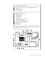
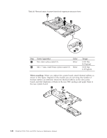
Table 36. Removal steps of system board and magnesium structure frame 2 3 2 2 1 1 Step 1 Screw (quantity) Hex stud, nylon-coated (2) Color Silver 2 M2 × 7 mm, wafer-head, nylon-coated (3) Silver Torque 0.392 Nm (4.0 kgfcm) 0.181 Nm (1.85 kgfcm) When installing: When you replace the system board, attach thermal rubbers as shown in this figure. Depend on the models you are servicing, the number of thermal rubbers are different. Check the thermal rubbers on the old system board, and find duplicates of them in the new FRU package and apply them to the new system board. a b c 128 ThinkPad T510, T510i, and W510 Hardware Maintenance Manual
-
 1
1 -
2
-
3
-
4
-
5
-
6
-
7
-
8
-
9
-
10
-
11
-
12
-
13
-
14
-
15
-
16
-
17
-
18
-
19
-
20
-
21
-
22
-
23
-
24
-
25
-
26
-
27
-
28
-
29
-
30
-
31
-
32
-
33
-
34
-
35
-
36
-
37
-
38
-
39
-
40
-
41
-
42
-
43
-
44
-
45
-
46
-
47
-
48
-
49
-
50
-
51
-
52
-
53
-
54
-
55
-
56
-
57
-
58
-
59
-
60
-
61
-
62
-
63
-
64
-
65
-
66
-
67
-
68
-
69
-
70
-
71
-
72
-
73
-
74
-
75
-
76
-
77
-
78
-
79
-
80
-
81
-
82
-
83
-
84
-
85
-
86
-
87
-
88
-
89
-
90
-
91
-
92
-
93
-
94
-
95
-
96
-
97
-
98
-
99
-
100
-
101
-
102
-
103
-
104
-
105
-
106
-
107
-
108
-
109
-
110
-
111
-
112
-
113
-
114
-
115
-
116
-
117
-
118
-
119
-
120
-
121
-
122
-
123
-
124
-
125
-
126
-
127
-
128
-
129
-
130
-
 131
131 -
 132
132 -
 133
133 -
 134
134 -
 135
135 -
 136
136 -
 137
137 -
 138
138 -
 139
139 -
 140
140 -
 141
141 -
142
-
143
-
144
-
145
-
146
-
147
-
148
-
149
-
150
-
151
-
152
-
153
-
154
-
155
-
156
-
157
-
158
-
159
-
160
-
161
-
162
-
163
-
164
-
165
-
166
-
167
-
168
-
169
-
170
-
171
-
172
-
173
-
174
-
175
-
176
-
177
-
178
-
179
-
180
-
181
-
182
-
183
-
184
-
185
-
186
-
187
-
188
-
189
-
190
-
191
-
192
-
193
-
194
-
195
-
196
-
197
-
198
-
199
-
200
-
201
-
202
-
203
-
204
-
205
-
206
-
207
-
208
-
209
-
210
-
211
-
212
 |
 |
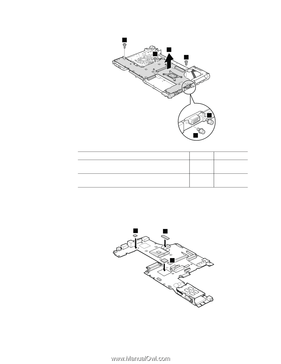
Table 36. Removal steps of system board and magnesium structure frame
3
1
1
2
2
2
Step
Screw (quantity)
Color
Torque
±1²
Hex stud, nylon-coated (2)
Silver
0.392 Nm
(4.0 kgfcm)
±2²
M2
×
7 mm, wafer-head, nylon-coated (3)
Silver
0.181 Nm
(1.85 kgfcm)
When installing:
When you replace the system board, attach thermal rubbers as
shown in this figure. Depend on the models you are servicing, the number of
thermal rubbers are different. Check the thermal rubbers on the old system
board, and find duplicates of them in the new FRU package and apply them to
the new system board.
b
c
a
128
ThinkPad T510, T510i, and W510 Hardware Maintenance Manual