Lenovo 7658 Hardware Maintenance Manual - Page 108
connectors
 |
UPC - 883609796495
View all Lenovo 7658 manuals
Add to My Manuals
Save this manual to your list of manuals |
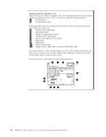
Page 108 highlights
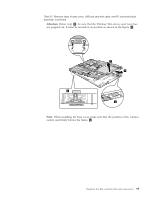
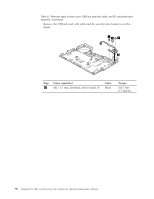
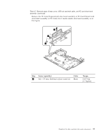
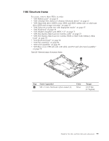
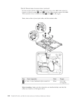
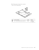
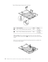
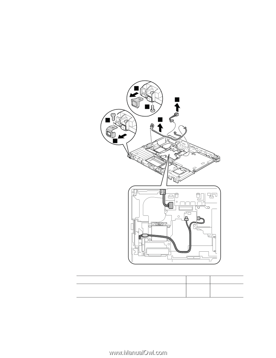
Table 28. Removal steps of structure frame (continued) For the models with the IEEE 1394 connector, remove the IEEE 1394 connector bracket as shown in step 2a and 3a . For the other models, remove the IEEE 1394 connector cover as shown in step 2b and 3b in this figure. Then, remove the ac power jack cable, and the modem cable. 3b 4 2b 2a 5 3a Step Screw (quantity) 2a or M2 × 3 mm, flat-head, nylon-coated (1) 2b Color Silver Torque 0.167 Nm (1.7 kgfcm) When installing: Make sure the connectors are attached firmly, and that the cables are routed as in the figure above. 100 ThinkPad T61, R61, and R61i (14.1-inch widescreen) Hardware Maintenance Manual
-
 1
1 -
2
-
3
-
4
-
5
-
6
-
7
-
8
-
9
-
10
-
11
-
12
-
13
-
14
-
15
-
16
-
17
-
18
-
19
-
20
-
21
-
22
-
23
-
24
-
25
-
26
-
27
-
28
-
29
-
30
-
31
-
32
-
33
-
34
-
35
-
36
-
37
-
38
-
39
-
40
-
41
-
42
-
43
-
44
-
45
-
46
-
47
-
48
-
49
-
50
-
51
-
52
-
53
-
54
-
55
-
56
-
57
-
58
-
59
-
60
-
61
-
62
-
63
-
64
-
65
-
66
-
67
-
68
-
69
-
70
-
71
-
72
-
73
-
74
-
75
-
76
-
77
-
78
-
79
-
80
-
81
-
82
-
83
-
84
-
85
-
86
-
87
-
88
-
89
-
90
-
91
-
92
-
93
-
94
-
95
-
96
-
97
-
98
-
99
-
100
-
101
-
102
-
 103
103 -
 104
104 -
 105
105 -
 106
106 -
 107
107 -
 108
108 -
 109
109 -
 110
110 -
 111
111 -
 112
112 -
 113
113 -
114
-
115
-
116
-
117
-
118
-
119
-
120
-
121
-
122
-
123
-
124
-
125
-
126
-
127
-
128
-
129
-
130
-
131
-
132
-
133
-
134
-
135
-
136
-
137
-
138
-
139
-
140
-
141
-
142
-
143
-
144
-
145
-
146
-
147
-
148
-
149
-
150
-
151
-
152
-
153
-
154
-
155
-
156
-
157
-
158
-
159
-
160
-
161
-
162
-
163
-
164
-
165
-
166
-
167
-
168
-
169
-
170
-
171
-
172
-
173
-
174
-
175
-
176
-
177
-
178
-
179
-
180
-
181
-
182
-
183
-
184
-
185
-
186
-
187
-
188
-
189
-
190
-
191
-
192
-
193
-
194
-
195
-
196
-
197
-
198
-
199
-
200
-
201
-
202
-
203
-
204
-
205
-
206
-
207
-
208
-
209
-
210
-
211
-
212
-
213
-
214
-
215
-
216
-
217
-
218
-
219
-
220
-
221
-
222
-
223
-
224
-
225
-
226
-
227
-
228
-
229
-
230
-
231
-
232
-
233
-
234
-
235
-
236
-
237
-
238
-
239
-
240
-
241
-
242
-
243
-
244
-
245
-
246
-
247
-
248
-
249
-
250
-
251
-
252
-
253
-
254
-
255
-
256
 |
 |
Table
28.
Removal
steps
of
structure
frame
(continued)
For
the
models
with
the
IEEE
1394
connector,
remove
the
IEEE
1394
connector
bracket
as
shown
in
step
±2a²
and
±3a²
.
For
the
other
models,
remove
the
IEEE
1394
connector
cover
as
shown
in
step
±2b²
and
±3b²
in
this
figure.
Then,
remove
the
ac
power
jack
cable,
and
the
modem
cable.
5
4
3a
2a
3b
2b
Step
Screw
(quantity)
Color
Torque
±2a²
or
±2b²
M2
×
3
mm,
flat-head,
nylon-coated
(1)
Silver
0.167
Nm
(1.7
kgfcm)
When
installing:
Make
sure
the
connectors
are
attached
firmly,
and
that
the
cables
are
routed
as
in
the
figure
above.
100
ThinkPad
T61,
R61,
and
R61i
(14.1-inch
widescreen)
Hardware
Maintenance
Manual