Lenovo 766513U Hardware Maintenance Manual - Page 112
Accelerometer
 |
UPC - 883609322984
View all Lenovo 766513U manuals
Add to My Manuals
Save this manual to your list of manuals |
Page 112 highlights
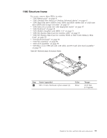
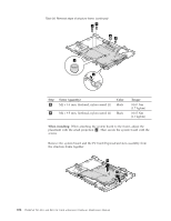
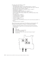
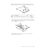
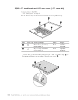
For access, remove these FRUs, in order: v "1010 Battery pack" on page 61 v "1020 Ultrabay Slim device or Ultrabay Enhanced device" on page 62 v "1030 Hard disk drive (HDD) cover, HDD, and HDD rubber rails or solid state drive (SSD) and storage converter" on page 63 v "1040 Palm rest or palm rest with fingerprint reader" on page 65 v "1060 Keyboard" on page 69 v "1070 Modem daughter card (MDC-1.5)" on page 71 v "1080 PCI Express Mini Card for wireless LAN" on page 73 v "1090 PCI Express Mini Card for wireless WAN or Intel Turbo Memory Mini Card" on page 75 v "1100 SIM card slot" on page 77 v "1110 Backup battery" on page 79 v "1120 Keyboard bezel" on page 80 v "1140 Fan assembly" on page 84 v "1150 CPU" on page 89 v "1160 LCD assembly" on page 90 v "1170 Base cover, USB sub card with cable, and PC Card slots bezel assembly" on page 93 v "1180 Structure frame" on page 99 Table 29. Removal steps of system board, PC Card/Express card slots assembly or PC Card/Smart card slots assembly or PC Card/4-in-1 media reader slot assembly Following components soldered on the top side of the system board are extremely sensitive. When you service the system board, avoid any kind of rough handling. a CPU b Video chip c MCH (Memory Controller Hub) d ICH (I/O Controller Hub) e Accelerometer chip for the HDD Active Protection System™ f Security chip b a c d f e 104 ThinkPad T61, R61, and R61i (14.1-inch widescreen) Hardware Maintenance Manual
-
 1
1 -
2
-
3
-
4
-
5
-
6
-
7
-
8
-
9
-
10
-
11
-
12
-
13
-
14
-
15
-
16
-
17
-
18
-
19
-
20
-
21
-
22
-
23
-
24
-
25
-
26
-
27
-
28
-
29
-
30
-
31
-
32
-
33
-
34
-
35
-
36
-
37
-
38
-
39
-
40
-
41
-
42
-
43
-
44
-
45
-
46
-
47
-
48
-
49
-
50
-
51
-
52
-
53
-
54
-
55
-
56
-
57
-
58
-
59
-
60
-
61
-
62
-
63
-
64
-
65
-
66
-
67
-
68
-
69
-
70
-
71
-
72
-
73
-
74
-
75
-
76
-
77
-
78
-
79
-
80
-
81
-
82
-
83
-
84
-
85
-
86
-
87
-
88
-
89
-
90
-
91
-
92
-
93
-
94
-
95
-
96
-
97
-
98
-
99
-
100
-
101
-
102
-
103
-
104
-
105
-
106
-
 107
107 -
 108
108 -
 109
109 -
 110
110 -
 111
111 -
 112
112 -
 113
113 -
 114
114 -
 115
115 -
 116
116 -
 117
117 -
118
-
119
-
120
-
121
-
122
-
123
-
124
-
125
-
126
-
127
-
128
-
129
-
130
-
131
-
132
-
133
-
134
-
135
-
136
-
137
-
138
-
139
-
140
-
141
-
142
-
143
-
144
-
145
-
146
-
147
-
148
-
149
-
150
-
151
-
152
-
153
-
154
-
155
-
156
-
157
-
158
-
159
-
160
-
161
-
162
-
163
-
164
-
165
-
166
-
167
-
168
-
169
-
170
-
171
-
172
-
173
-
174
-
175
-
176
-
177
-
178
-
179
-
180
-
181
-
182
-
183
-
184
-
185
-
186
-
187
-
188
-
189
-
190
-
191
-
192
-
193
-
194
-
195
-
196
-
197
-
198
-
199
-
200
-
201
-
202
-
203
-
204
-
205
-
206
-
207
-
208
-
209
-
210
-
211
-
212
-
213
-
214
-
215
-
216
-
217
-
218
-
219
-
220
-
221
-
222
-
223
-
224
-
225
-
226
-
227
-
228
-
229
-
230
-
231
-
232
-
233
-
234
-
235
-
236
-
237
-
238
-
239
-
240
-
241
-
242
-
243
-
244
-
245
-
246
-
247
-
248
-
249
-
250
-
251
-
252
-
253
-
254
-
255
-
256
 |
 |
