Lenovo B40-45 Laptop Hardware Maintenance Manual - Lenovo B40-xx Notebook - Page 50
Removal, steps, finger, print, power, board, continued, adhesive, cavity, direction, arrow
 |
View all Lenovo B40-45 Laptop manuals
Add to My Manuals
Save this manual to your list of manuals |
Page 50 highlights
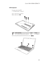
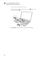
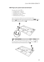
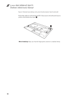
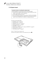
Lenovo B40-30/B40-45/ B40-70 Hardware Maintenance Manual Figure 9. Removal steps of finger print, power board and power board (continued) Peel off the adhesive of the led board FPC. Then remove the led board from its cavity in the direction by arrow 7. 7 When installing: Make sure that the finger print connector is attached firmly. 46
-
 1
1 -
2
-
3
-
4
-
5
-
6
-
7
-
8
-
9
-
10
-
11
-
12
-
13
-
14
-
15
-
16
-
17
-
18
-
19
-
20
-
21
-
22
-
23
-
24
-
25
-
26
-
27
-
28
-
29
-
30
-
31
-
32
-
33
-
34
-
35
-
36
-
37
-
38
-
39
-
40
-
41
-
42
-
43
-
44
-
 45
45 -
 46
46 -
 47
47 -
 48
48 -
 49
49 -
 50
50 -
 51
51 -
 52
52 -
 53
53 -
 54
54 -
 55
55 -
56
-
57
-
58
-
59
-
60
-
61
-
62
-
63
-
64
-
65
-
66
-
67
-
68
-
69
-
70
-
71
-
72
-
73
-
74
-
75
-
76
-
77
-
78
-
79
-
80
-
81
-
82
-
83
-
84
-
85
 |
 |

Lenovo B40-30/B40-45/ B40-70
Hardware Maintenance Manual
46
Figure
9.
Removal
steps
of
finger
print,
power
board
and
power
board
(continued)
Peel
off
the
adhesive
of
the
led
board
FPC.
Then
remove
the
led
board
from
its
cavity
in
the
direction
by
arrow
.
When installing:
Make
sure
that
the
finger
print
connector
is
attached
firmly.
7
7