Lenovo B575 Hardware Maintenance Manual - Page 64
Removal steps of LCD panel, LCD cable and hinges continued, Remove four screws
 |
View all Lenovo B575 manuals
Add to My Manuals
Save this manual to your list of manuals |
Page 64 highlights
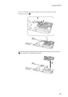
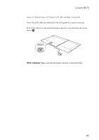
Lenovo B575 Hardware Maintenance Manual Figure 16. Removal steps of LCD panel, LCD cable and hinges (continued) Remove four screws d and remove the hinges in the direction shown by arrow e. 4 5 4 4 5 4 Step d Screw (quantity) M2 × 2.5, flat-head, nylokcoated (4) Color Black Torque 1.5 kgfcm 60
-
 1
1 -
2
-
3
-
4
-
5
-
6
-
7
-
8
-
9
-
10
-
11
-
12
-
13
-
14
-
15
-
16
-
17
-
18
-
19
-
20
-
21
-
22
-
23
-
24
-
25
-
26
-
27
-
28
-
29
-
30
-
31
-
32
-
33
-
34
-
35
-
36
-
37
-
38
-
39
-
40
-
41
-
42
-
43
-
44
-
45
-
46
-
47
-
48
-
49
-
50
-
51
-
52
-
53
-
54
-
55
-
56
-
57
-
58
-
 59
59 -
 60
60 -
 61
61 -
 62
62 -
 63
63 -
 64
64 -
 65
65 -
 66
66 -
 67
67 -
 68
68 -
 69
69 -
70
-
71
-
72
-
73
-
74
-
75
-
76
-
77
-
78
-
79
-
80
-
81
-
82
-
83
-
84
-
85
-
86
 |
 |

Lenovo B575 Hardware Maintenance Manual
60
Figure 16. Removal steps of LCD panel, LCD cable and hinges (continued)
Remove four screws
and remove the hinges in the direction shown by arrow
Step
Screw (quantity)
Color
Torque
M2 × 2.5, flat-head, nylokcoated (4)
Black
1.5 kgfcm
d
e
4
4
4
4
5
5
d