Lenovo B575e Lenovo B575e Hardware Maintenance Manual - Page 85
Locations, Front view
 |
View all Lenovo B575e manuals
Add to My Manuals
Save this manual to your list of manuals |
Page 85 highlights
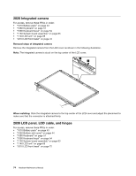
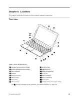
Chapter 8. Locations This chapter introduces the locations of the computer hardware components. Front view 1 2 16 15 4 14 3 4 13 12 5 6 7 11 8 9 10 Figure 1. Lenovo B575e front view 1 Integrated camera (on some models) 2 Wireless antennas (on some models) 3 Status indicators1 4 Speakers 5 Ethernet connector 6 USB connector 7 Optical drive 8 USB connector 9 Microphone jack 10 Headphone jack 11 Media card reader slot 12 Touch pad 13 Status indicators2 14 Built-in microphone 15 Power button 16 OneKey Recovery Pro program button 1 and 2 : For the description of the indicators, see "Status indicators" on page 38. © Copyright Lenovo 2012 79
-
 1
1 -
2
-
3
-
4
-
5
-
6
-
7
-
8
-
9
-
10
-
11
-
12
-
13
-
14
-
15
-
16
-
17
-
18
-
19
-
20
-
21
-
22
-
23
-
24
-
25
-
26
-
27
-
28
-
29
-
30
-
31
-
32
-
33
-
34
-
35
-
36
-
37
-
38
-
39
-
40
-
41
-
42
-
43
-
44
-
45
-
46
-
47
-
48
-
49
-
50
-
51
-
52
-
53
-
54
-
55
-
56
-
57
-
58
-
59
-
60
-
61
-
62
-
63
-
64
-
65
-
66
-
67
-
68
-
69
-
70
-
71
-
72
-
73
-
74
-
75
-
76
-
77
-
78
-
79
-
 80
80 -
 81
81 -
 82
82 -
 83
83 -
 84
84 -
 85
85 -
 86
86 -
 87
87 -
 88
88 -
 89
89 -
 90
90 -
91
-
92
-
93
-
94
-
95
-
96
-
97
-
98
-
99
-
100
-
101
-
102
 |
 |
Chapter 8.
Locations
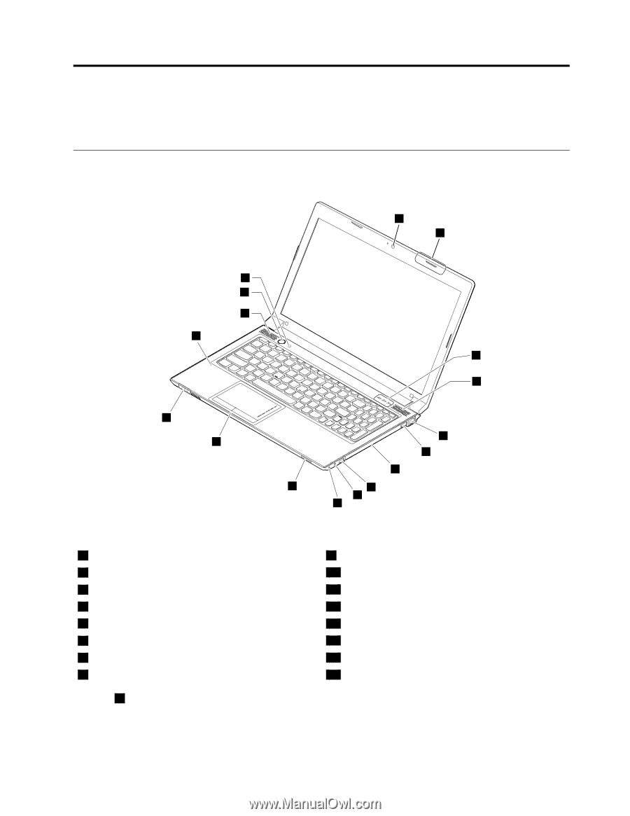
This chapter introduces the locations of the computer hardware components.
Front view
1
2
4
5
6
7
13
14
15
4
16
12
8
9
10
11
3
Figure 1. Lenovo B575e front view
1
Integrated camera (on some models)
9
Microphone jack
2
Wireless antennas (on some models)
10
Headphone jack
3
Status indicators
1
11
Media card reader slot
4
Speakers
12
Touch pad
5
Ethernet connector
13
Status indicators
2
6
USB connector
14
Built-in microphone
7
Optical drive
15
Power button
8
USB connector
16
OneKey Recovery Pro program button
1
and
2
: For the description of the indicators, see “Status indicators” on page 38.
© Copyright Lenovo 2012
79