Lenovo G575 Hardware Maintenance Manual - Page 61
Removal steps of LCD unit continued, the cables to be damaged by the cable guides
 |
View all Lenovo G575 manuals
Add to My Manuals
Save this manual to your list of manuals |
Page 61 highlights
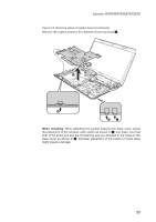
Lenovo G470/G475/G570/G575 Figure 14. Removal steps of LCD unit (continued) 33 33 2 2 When installing: •• Route the antenna cables along the cable guides. As you route the cables, make sure that they are not subjected to any tension. Tension could cause the cables to be damaged by the cable guides, or a wire to be broken. Step 3 Screw (quantity) M2.5 × 5 mm, flat-head, nylon-coated (4) Color Black Torque 2.0kgfcm 57
-
 1
1 -
2
-
3
-
4
-
5
-
6
-
7
-
8
-
9
-
10
-
11
-
12
-
13
-
14
-
15
-
16
-
17
-
18
-
19
-
20
-
21
-
22
-
23
-
24
-
25
-
26
-
27
-
28
-
29
-
30
-
31
-
32
-
33
-
34
-
35
-
36
-
37
-
38
-
39
-
40
-
41
-
42
-
43
-
44
-
45
-
46
-
47
-
48
-
49
-
50
-
51
-
52
-
53
-
54
-
55
-
 56
56 -
 57
57 -
 58
58 -
 59
59 -
 60
60 -
 61
61 -
 62
62 -
 63
63 -
 64
64 -
 65
65 -
 66
66 -
67
-
68
-
69
-
70
-
71
-
72
-
73
-
74
-
75
-
76
-
77
-
78
-
79
-
80
-
81
-
82
-
83
-
84
-
85
-
86
-
87
-
88
-
89
-
90
-
91
-
92
-
93
-
94
 |
 |

57
Lenovo G470/G475/G570/G575
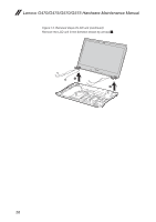
Figure 14. Removal steps of LCD unit (continued)
2
2
3
3
3
3
When installing:
Route the antenna cables along the cable guides. As you route the cables,
•
make sure that they are not subjected to any tension. Tension could cause
the cables to be damaged by the cable guides, or a wire to be broken.
Step
Screw (quantity)
Color
Torque
3
M2.5 × 5 mm, flat-head, nylon-coated (4)
Black
2.0kgfcm