Lenovo IdeaPad Flex 14 Hardware Maintenance Manual - IdeaPad Flex14, Flex14D, - Page 53
Flex 15/Flex 15D, Removal steps of fan assembly and heat sink assembly continued
 |
View all Lenovo IdeaPad Flex 14 manuals
Add to My Manuals
Save this manual to your list of manuals |
Page 53 highlights
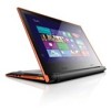
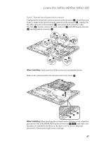
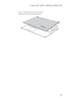
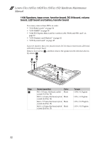
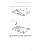
Lenovo Flex 14/Flex 14D/Flex 15/Flex 15D Figure 8. Removal steps of fan assembly and heat sink assembly (continued) Unplug the fan connector in the direction shown by arrow b. Flex 15/Flex 15D: b When installing: Make sure that the fan connector is attached firmly to the system board. Lift the fan assembly in the direction shown by arrow c. Be careful not to damage the connector. Flex 14/Flex 14D: c Flex 15/Flex 15D: c 49
-
 1
1 -
2
-
3
-
4
-
5
-
6
-
7
-
8
-
9
-
10
-
11
-
12
-
13
-
14
-
15
-
16
-
17
-
18
-
19
-
20
-
21
-
22
-
23
-
24
-
25
-
26
-
27
-
28
-
29
-
30
-
31
-
32
-
33
-
34
-
35
-
36
-
37
-
38
-
39
-
40
-
41
-
42
-
43
-
44
-
45
-
46
-
47
-
 48
48 -
 49
49 -
 50
50 -
 51
51 -
 52
52 -
 53
53 -
 54
54 -
 55
55 -
 56
56 -
 57
57 -
 58
58 -
59
-
60
-
61
-
62
-
63
-
64
-
65
-
66
-
67
-
68
-
69
-
70
-
71
-
72
-
73
-
74
-
75
-
76
-
77
-
78
-
79
-
80
-
81
-
82
-
83
-
84
-
85
-
86
-
87
-
88
-
89
-
90
 |
 |

Lenovo Flex 14/Flex 14D/Flex 15/Flex 15D
49
Figure 8. Removal steps of fan assembly and heat sink assembly (continued)
Unplug the fan connector in the direction shown by arrow
Flex 15/Flex 15D:
When installing:
Make sure that the fan connector is attached firmly to the
system board.
Lift the fan assembly in the direction shown by arrow
. Be careful not to
damage the connector.
Flex 14/Flex 14D:
Flex 15/Flex 15D:
b
b
c
c
c