Lenovo IdeaPad N585 IdeaPad P580, P585, N580, N581, N585, N586 Hardware Mainta - Page 44
DIMM, Removal steps of DIMM
 |
View all Lenovo IdeaPad N585 manuals
Add to My Manuals
Save this manual to your list of manuals |
Page 44 highlights
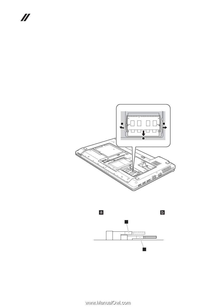
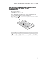
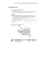
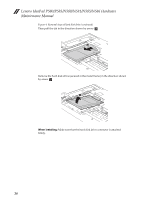
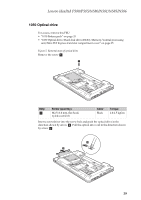
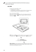
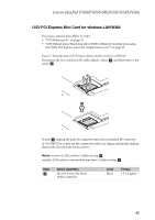
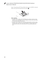
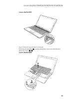
Lenovo IdeaPad P580/P585/N580/N581/N585/N586 Hardware Maintenance Manual 1060 DIMM For access, remove these FRUs in order: • "1010 Battery pack" on page 33 • "1030 Optical drive/Hard disk drive (HDD)/Memory/Central processing unit/Mini PCI Express Card slot compartment cover" on page 35 Figure 6. Removal steps of DIMM Release the two latches on both edges of the socket at the same time in the direction shown by arrows a, and then unplug the DIMM in the direction shown by arrow b. 1 1 2 Note: If only one DIMM is used on the computer you are servicing, the card must be installed in SLOT-0 ( : lower slot), but not in SLOT-1 ( : upper slot). z b a When installing: Insert the notched end of the DIMM into the socket. Push the DIMM firmly, and pivot it until it snaps into the place. Make sure that it is firmly fixed in the slot and difficult to be moved. 40
-
 1
1 -
2
-
3
-
4
-
5
-
6
-
7
-
8
-
9
-
10
-
11
-
12
-
13
-
14
-
15
-
16
-
17
-
18
-
19
-
20
-
21
-
22
-
23
-
24
-
25
-
26
-
27
-
28
-
29
-
30
-
31
-
32
-
33
-
34
-
35
-
36
-
37
-
38
-
 39
39 -
 40
40 -
 41
41 -
 42
42 -
 43
43 -
 44
44 -
 45
45 -
 46
46 -
 47
47 -
 48
48 -
 49
49 -
50
-
51
-
52
-
53
-
54
-
55
-
56
-
57
-
58
-
59
-
60
-
61
-
62
-
63
-
64
-
65
-
66
-
67
-
68
-
69
-
70
-
71
-
72
-
73
-
74
-
75
-
76
-
77
-
78
-
79
-
80
-
81
-
82
-
83
-
84
-
85
-
86
-
87
-
88
-
89
-
90
-
91
-
92
-
93
-
94
-
95
-
96
-
97
-
98
-
99
-
100
-
101
-
102
-
103
 |
 |