Lenovo IdeaPad S10-3s Lenovo IdeaPad S10-3s Hardware Maintenance Manual V2.0 - Page 62
Antenna assembly and LCD cover
 |
View all Lenovo IdeaPad S10-3s manuals
Add to My Manuals
Save this manual to your list of manuals |
Page 62 highlights
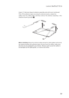
IdeaPad S10-3s Hardware Maintenance Manual 1170 Antenna assembly and LCD cover For access, remove these FRUs in order: •• "1010 Battery pack" on page 34 •• "1020 Dummy cards" on page 35 •• "1040 Keyboard" on page 37 •• "1050 Base cover" on page 39 •• "1060 PCI Express Mini Card for wireless LAN" on page 42 •• "1070 LCD unit" on page 44 •• "1140 LCD front bezel" on page 54 •• "1150 LCD panel, LCD cable and hinges" on page 55 Figure 17. Removal steps of antenna assembly and LCD cover Detach the connector on the button board in the direction shown by arrow 1. 1 When installing: Make sure that the connector is attached firmly. Remove the power board on the left and the button board on the right in the direction shown by arrows 2. 2 2 58
-
 1
1 -
2
-
3
-
4
-
5
-
6
-
7
-
8
-
9
-
10
-
11
-
12
-
13
-
14
-
15
-
16
-
17
-
18
-
19
-
20
-
21
-
22
-
23
-
24
-
25
-
26
-
27
-
28
-
29
-
30
-
31
-
32
-
33
-
34
-
35
-
36
-
37
-
38
-
39
-
40
-
41
-
42
-
43
-
44
-
45
-
46
-
47
-
48
-
49
-
50
-
51
-
52
-
53
-
54
-
55
-
56
-
 57
57 -
 58
58 -
 59
59 -
 60
60 -
 61
61 -
 62
62 -
 63
63 -
 64
64 -
 65
65 -
 66
66 -
 67
67 -
68
-
69
-
70
-
71
-
72
-
73
-
74
-
75
-
76
-
77
-
78
-
79
-
80
-
81
 |
 |

58
IdeaPad S10-3s Hardware Maintenance Manual
1170 Antenna assembly and LCD cover
For access, remove these FRUs in order:
•
“1010 Battery pack” on page 34
•
“1020 Dummy cards” on page 35
•
“1040 Keyboard” on page 37
•
“1050 Base cover” on page 39
•
“1060 PCI Express Mini Card for wireless LAN” on page 42
•
“1070 LCD unit” on page 44
•
“1140 LCD front bezel” on page 54
•
“1150 LCD panel, LCD cable and hinges” on page 55
Figure 17. Removal steps of antenna assembly and LCD cover
Detach the connector on the button board in the direction shown by arrow
1
.
1
When installing:
Make sure that the connector is attached firmly.
Remove the power board on the left and the button board on the right in the
direction shown by arrows
2
.
2
2