Lenovo IdeaPad Z560 Lenovo IdeaPad Z560/Z565 Hardware Maintenance Manual - Page 56
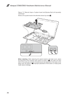
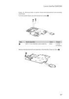
Speakers, power board and touch inductive panel, Turn over the keyboard bezel, remove four screws
 |
View all Lenovo IdeaPad Z560 manuals
Add to My Manuals
Save this manual to your list of manuals |
Page 56 highlights
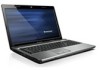
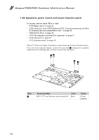
Ideapad Z560/Z565 Hardware Maintenance Manual 1120 Speakers, power board and touch inductive panel For access, remove these FRUs in order: •• "1010 Battery pack" on page 34 •• "1030 Hard disk drive (HDD)/Memory/CPU (Central processing unit)/Mini PCI ExpressCard slot compartment cover " on page 36 •• "1050 Optical drive" on page 39 •• "1070 Fan assembly and Heat Sink assembly" on page 41 •• "1100 Keyboard" on page 47 •• "1110 Keyboard bezel" on page 49 Figure 12. Removal steps of speakers, power board and touch inductive panel Turn over the keyboard bezel, remove four screws 1, release the speaker cables from the cable guides, and then remove the speakers. 11 11 Step 1 Screw (quantity) M2.5 × 5.7 mm, flat-head, nylon-coated (4) Color Black Torque 0.6 Nm (6 kgfcm) 52
-
 1
1 -
2
-
3
-
4
-
5
-
6
-
7
-
8
-
9
-
10
-
11
-
12
-
13
-
14
-
15
-
16
-
17
-
18
-
19
-
20
-
21
-
22
-
23
-
24
-
25
-
26
-
27
-
28
-
29
-
30
-
31
-
32
-
33
-
34
-
35
-
36
-
37
-
38
-
39
-
40
-
41
-
42
-
43
-
44
-
45
-
46
-
47
-
48
-
49
-
50
-
 51
51 -
 52
52 -
 53
53 -
 54
54 -
 55
55 -
 56
56 -
 57
57 -
 58
58 -
 59
59 -
 60
60 -
 61
61 -
62
-
63
-
64
-
65
-
66
-
67
-
68
-
69
-
70
-
71
-
72
-
73
-
74
-
75
-
76
-
77
-
78
-
79
-
80
-
81
-
82
-
83
-
84
-
85
-
86
-
87
-
88
-
89
-
90
 |
 |
