Lenovo IdeaPad Z570 Lenovo Z370/Z470/Z570 Hardware Maintenance Manual V1.0 - Page 65
LCD unit
 |
View all Lenovo IdeaPad Z570 manuals
Add to My Manuals
Save this manual to your list of manuals |
Page 65 highlights
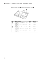
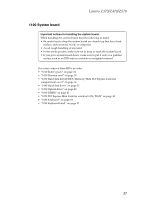
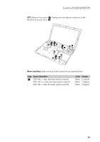
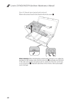
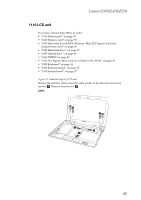
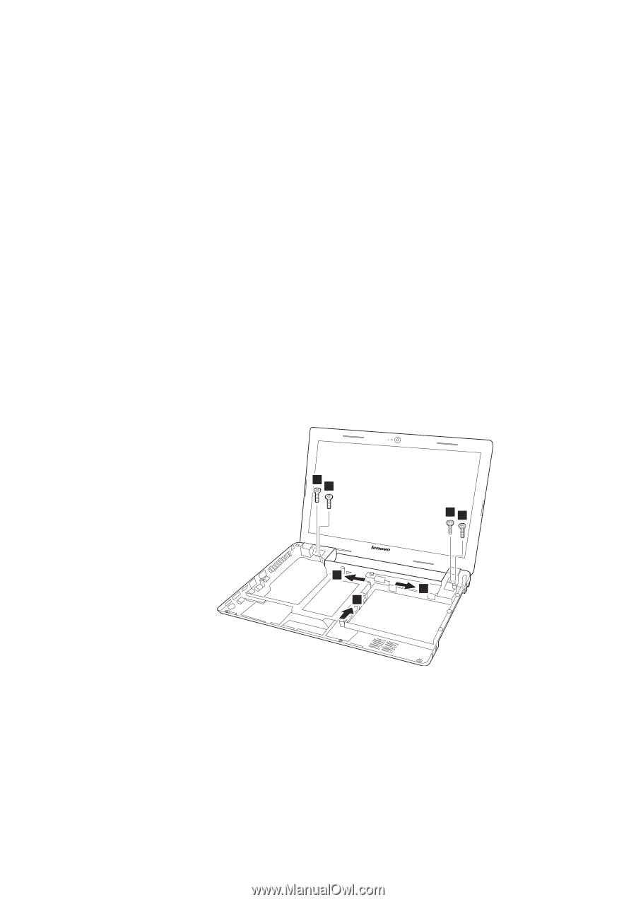
Lenovo Z370/Z470/Z570 1110 LCD unit For access, remove these FRUs in order: • "1010 Battery pack" on page 34 • "1020 Dummy card" on page 35 • "1030 Hard disk drive(HDD)/Memory/Mini PCI Express Card slot compartment cover" on page 36 • "1040 Hard disk drive" on page 37 • "1050 Optical drive" on page 40 • "1060 DIMM" on page 41 • "1070 PCI Express Mini Card for wireless LAN/WAN" on page 42 • "1080 Keyboard" on page 44 • "1090 Keyboard bezel" on page 47 • "1100 System board" on page 57 Figure 11. Removal steps of LCD unit Release the antenna cables from the cable guides in the direction shown by arrows a. Remove four screws b. Z370: 2 2 1 1 22 1 61
-
 1
1 -
2
-
3
-
4
-
5
-
6
-
7
-
8
-
9
-
10
-
11
-
12
-
13
-
14
-
15
-
16
-
17
-
18
-
19
-
20
-
21
-
22
-
23
-
24
-
25
-
26
-
27
-
28
-
29
-
30
-
31
-
32
-
33
-
34
-
35
-
36
-
37
-
38
-
39
-
40
-
41
-
42
-
43
-
44
-
45
-
46
-
47
-
48
-
49
-
50
-
51
-
52
-
53
-
54
-
55
-
56
-
57
-
58
-
59
-
 60
60 -
 61
61 -
 62
62 -
 63
63 -
 64
64 -
 65
65 -
 66
66 -
 67
67 -
 68
68 -
 69
69 -
 70
70 -
71
-
72
-
73
-
74
-
75
-
76
-
77
-
78
-
79
-
80
-
81
-
82
-
83
-
84
-
85
-
86
-
87
-
88
-
89
-
90
-
91
-
92
-
93
-
94
-
95
-
96
-
97
-
98
-
99
-
100
-
101
-
102
-
103
-
104
-
105
-
106
-
107
-
108
-
109
-
110
-
111
-
112
-
113
-
114
-
115
-
116
-
117
-
118
-
119
-
120
 |
 |
Lenovo Z370/Z470/Z570
61
1110 LCD unit
For access, remove these FRUs in order:
•
“1010 Battery pack” on page 34
•
“1020 Dummy card” on page 35
•
“1030 Hard disk drive(HDD)/Memory/Mini PCI Express Card slot
compartment cover” on page 36
•
“1040 Hard disk drive” on page 37
•
“1050 Optical drive” on page 40
•
“1060 DIMM” on page 41
•
“1070 PCI Express Mini Card for wireless LAN/WAN” on page 42
•
“1080 Keyboard” on page 44
•
“1090 Keyboard bezel” on page 47
•
“1100 System board” on page 57
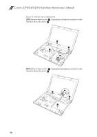
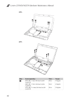
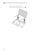
Figure 11. Removal steps of LCD unit
Release the antenna cables from the cable guides in the direction shown by
arrows
. Remove four screws
.
Z370:
a
b
1
1
1
2
2
2
2