Lenovo PC 300PL Techical Information Manual - Page 27
Component outputs, Power supply
 |
View all Lenovo PC 300PL manuals
Add to My Manuals
Save this manual to your list of manuals |
Page 27 highlights
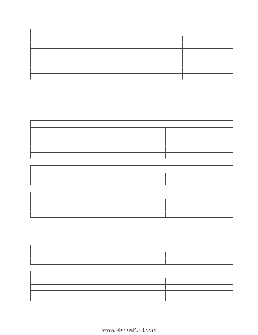
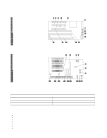
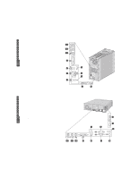
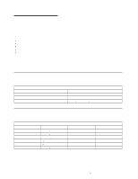
Chapter 4. Power supply Figure 9. Power output (200 watts) Output voltage Regulation +5 volts +5% to -4% +12 volts ±5% −12 volts +10% to -9% −5 volts ±10% + 3.3 volts ±2% +5 volts (auxiliary) ±5% Minimum current 1.5 A 0.2 A 0.0 A 0.0 A 0.0 A 0.005 A Maximum current 20.0 A 8.0 A 0.4 A 0.3 A 20.0 A 0.72 A Component outputs The power supply provides separate voltage sources for the system board and internal storage devices. The following figures show the approximate power that is provided for specific system components. Many components draw less current than the maximum shown. Figure 10. System board Supply voltage +3.3 V dc +5.0 V dc +12.0 V dc −12.0 V dc Maximum current 3000 mA 4000 mA 25.0 mA 25.0 mA Regulation limits +5.0% to −5.0% +5.0% to −4.0% +5.0% to −5.0% +10.0% to −9.0% Figure 11. Keyboard port Supply voltage +5.0 V dc Maximum current 275 mA Regulation limits +5.0% to −4.0% Figure 12. PCI-bus adapters (per slot) Supply voltage Maximum current +5.0 V dc 2000 mA +3.3 V dc 3030 mA Regulation limits +5.0% to −4.0% +5.0% to −4.0% Note: For each PCI connector, the maximum power consumption is rated at 10 watts for +5 V dc and +3.3 V dc combined. Typical power budget assumptions use 7.5 watts per adapter. If maximum power is used, then the overall system configuration will be limited in performance. Figure 13. USB port Supply voltage +5.0 V dc Maximum current 500 mA Regulation limits +5.0% to −4.0% Figure 14. Internal DASD Supply voltage +5.0 V dc +12.0 V dc Maximum current 1400 mA 1500 mA at startup, 400 mA when active Regulation limits +5.0% to −5.0% +5.0% to −5.0% Chapter 4. Power supply 19
-
 1
1 -
2
-
3
-
4
-
5
-
6
-
7
-
8
-
9
-
10
-
11
-
12
-
13
-
14
-
15
-
16
-
17
-
18
-
19
-
20
-
21
-
 22
22 -
 23
23 -
 24
24 -
 25
25 -
 26
26 -
 27
27 -
 28
28 -
 29
29 -
 30
30 -
 31
31 -
 32
32 -
33
-
34
-
35
-
36
-
37
-
38
-
39
-
40
-
41
-
42
-
43
-
44
-
45
-
46
-
47
-
48
-
49
-
50
-
51
-
52
-
53
-
54
 |
 |