Lenovo PC 300PL Technical Information Manual for IBM PC300GL (Type 6563, 6564, - Page 24
Cable connectors, Connector panel, 300GL and PC 300PL User Guide
 |
View all Lenovo PC 300PL manuals
Add to My Manuals
Save this manual to your list of manuals |
Page 24 highlights
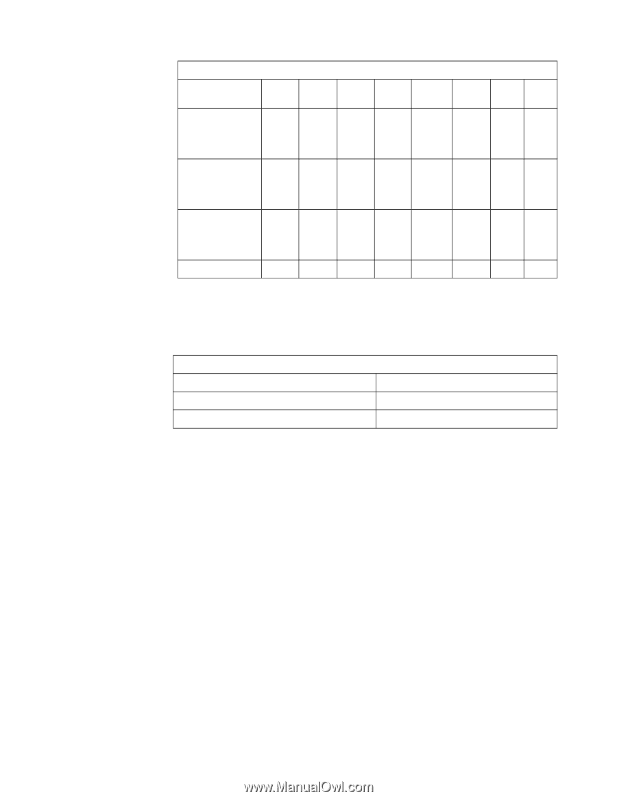
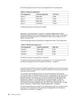
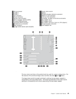
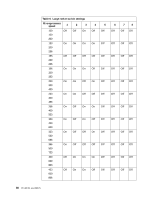
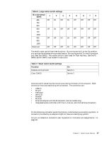
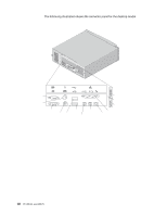
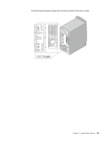
Table 6. Large rocker switch settings Microprocessor speed 1 2 3 4 5 6 7 8 466 Off On Off On Off Off Off Off 700 933 500 Off On Off Off Off Off Off Off 750 1000 533 800 1066 Off Off On On Off Off Off Off Reserved Off Off Off On Off Off Off Off The small rocker switch has three functions. By moving switch 1 to the On position, you activate the diskette write-protect feature. By moving switch 2 to the On position, you clear the CMOS. This rocker switch is also used for flash recovery. See the PC 300GL and PC 300PL User Guide for instruction. Table 7. Small rocker switch settings Function Diskette write-protect Clear CMOS On Switch 1 Switch 2 Cable connectors Connections for attaching devices are provided on the back of the computer. Each connection has a corresponding device symbol. The connectors are: • USB (2) • Mouse • Keyboard • Serial (2) • Parallel • Monitor • Ethernet adapter with RJ-45 connector (some models only) • Integrated audio controller with line in, line out, and microphone connectors Connector panel On the following connector panel illustrations, note the device connection symbols. A connector provided by an adapter might not have an identifying symbol. For pin-out details on connectors, see "Appendix A. Connector pin assignments," on page 33. Chapter 2. System board features 17
-
 1
1 -
2
-
3
-
4
-
5
-
6
-
7
-
8
-
9
-
10
-
11
-
12
-
13
-
14
-
15
-
16
-
17
-
18
-
 19
19 -
 20
20 -
 21
21 -
 22
22 -
 23
23 -
 24
24 -
 25
25 -
 26
26 -
 27
27 -
 28
28 -
 29
29 -
30
-
31
-
32
-
33
-
34
-
35
-
36
-
37
-
38
-
39
-
40
-
41
-
42
-
43
-
44
-
45
-
46
-
47
-
48
-
49
-
50
-
51
-
52
-
53
-
54
-
55
-
56
-
57
-
58
-
59
-
60
-
61
-
62
-
63
-
64
-
65
-
66
-
67
-
68
-
69
 |
 |