Lenovo ThinkCentre M51 User Manual - Page 28
Installing, memory, module
 |
View all Lenovo ThinkCentre M51 manuals
Add to My Manuals
Save this manual to your list of manuals |
Page 28 highlights
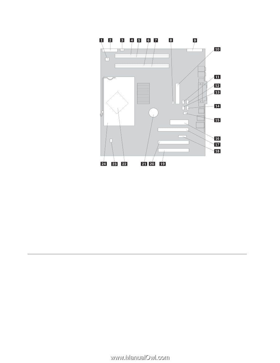
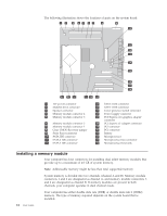
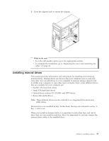
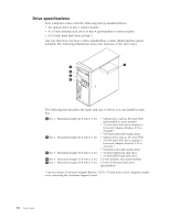
The following illustration shows the locations of parts on the system board. 1 12V power connector 2 Diskette drive connector 3 Speaker connector 4 Memory module connector 4 5 Memory module connector 3 6 Memory module connector 2 7 Memory module connector 1 8 Clear CMOS/Recovery jumper 9 Front Panel connector 10 PATA IDE connector 11 SATA 4 IDE connector 12 SATA 3 IDE connector 13 SATA 2 IDE connector 14 SATA 1 IDE connector 15 Cover presence switch connector 16 Power supply connector 17 PCI Express x16 graphics adapter connector 18 PCI Express x1 adapter connector 19 PCI connector 20 PCI connector 21 Battery 22 Microprocessor 23 Microprocessor fan connector 24 Microprocessor heat sink Installing a memory module Your computer has four connectors for installing dual inline memory modules that provide up to a maximum of 4.0 GB of system memory. Note: Addressable memory might be less than total supported memory. System memory is divided into two channels (channel A and B). Memory module connectors 1 and 2 are designated as channel A, and memory module connectors 3 and 4 are designated as channel B. If memory modules are present in both channels, your computer operates in dual channel mode. Your computer has either double data rate (DDR) or double data rate 2 (DDR2) memory. The type of memory required depends on the system board that is installed. 12 User Guide
-
 1
1 -
2
-
3
-
4
-
5
-
6
-
7
-
8
-
9
-
10
-
11
-
12
-
13
-
14
-
15
-
16
-
17
-
18
-
19
-
20
-
21
-
22
-
 23
23 -
 24
24 -
 25
25 -
 26
26 -
 27
27 -
 28
28 -
 29
29 -
 30
30 -
 31
31 -
 32
32 -
 33
33 -
34
-
35
-
36
-
37
-
38
-
39
-
40
-
41
-
42
-
43
-
44
-
45
-
46
-
47
-
48
-
49
-
50
-
51
-
52
-
53
-
54
-
55
-
56
-
57
-
58
-
59
-
60
-
61
-
62
 |
 |