Lenovo ThinkPad 560 TP 560Z Technical Reference Manual - Page 31
Diskette Drive Connector, 9 shows
 |
View all Lenovo ThinkPad 560 manuals
Add to My Manuals
Save this manual to your list of manuals |
Page 31 highlights
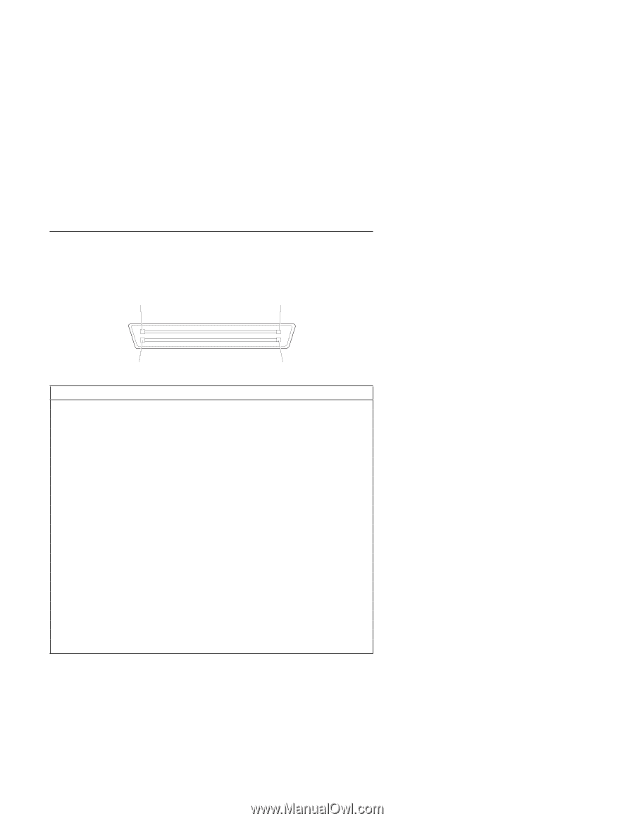
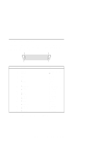
Diskette Drive Connector The external diskette drive is connected through the diskette drive connector, on the left side of the computer. Figure 2-9 shows the pin assignments of the connector: 25 1 26 2 Pin Signal 1 GND 2 DRATE1 3 VCC5B 4- 5 GND 6- 7 GND 8 −INDEX 9- 10 - 11 −DRVSEL0 12 DRATE0 13 −MOTEN0 14 - 15 −FDIR 16 −FSTEP 17 WRDATA 18 −FWREN 19 GND 20 −TRAK0 21 - 22 −FWPROTECT 23 RDDATA 24 −FSIDE1SEL 25 - 26 −DISKCHG Type Ground Data Rate Select 1 +5V dc Reserved Ground Reserved Ground Index Reserved Reserved Drive Select 0 Data Rate Select 0 Motor Enable 0 Reserved Direction In Step Write Data Write Enable Ground Track 0 Reserved Write Protect Read Data Side 1 Select Reserved Disk Change Figure 2-9. Diskette Drive Connector Pin Assignments ThinkPad 560Z System Board 2-13
-
 1
1 -
2
-
3
-
4
-
5
-
6
-
7
-
8
-
9
-
10
-
11
-
12
-
13
-
14
-
15
-
16
-
17
-
18
-
19
-
20
-
21
-
22
-
23
-
24
-
25
-
 26
26 -
 27
27 -
 28
28 -
 29
29 -
 30
30 -
 31
31 -
 32
32 -
 33
33 -
 34
34 -
 35
35 -
 36
36 -
37
-
38
-
39
-
40
-
41
-
42
-
43
-
44
-
45
-
46
-
47
-
48
-
49
-
50
-
51
-
52
-
53
-
54
-
55
-
56
-
57
-
58
-
59
-
60
-
61
-
62
-
63
-
64
-
65
-
66
-
67
-
68
-
69
-
70
-
71
-
72
-
73
-
74
-
75
-
76
-
77
-
78
-
79
-
80
-
81
-
82
-
83
-
84
-
85
-
86
-
87
-
88
-
89
-
90
-
91
-
92
-
93
-
94
-
95
-
96
-
97
-
98
-
99
-
100
-
101
-
102
-
103
-
104
-
105
-
106
-
107
-
108
-
109
-
110
-
111
-
112
-
113
-
114
-
115
-
116
-
117
-
118
-
119
-
120
-
121
-
122
-
123
-
124
-
125
-
126
-
127
-
128
-
129
-
130
-
131
-
132
-
133
-
134
 |
 |