Lenovo ThinkPad Edge E531 Hardware Maintenance Manual - Page 91
System board assembly, Removal steps of the microprocessor, When installing
 |
View all Lenovo ThinkPad Edge E531 manuals
Add to My Manuals
Save this manual to your list of manuals |
Page 91 highlights
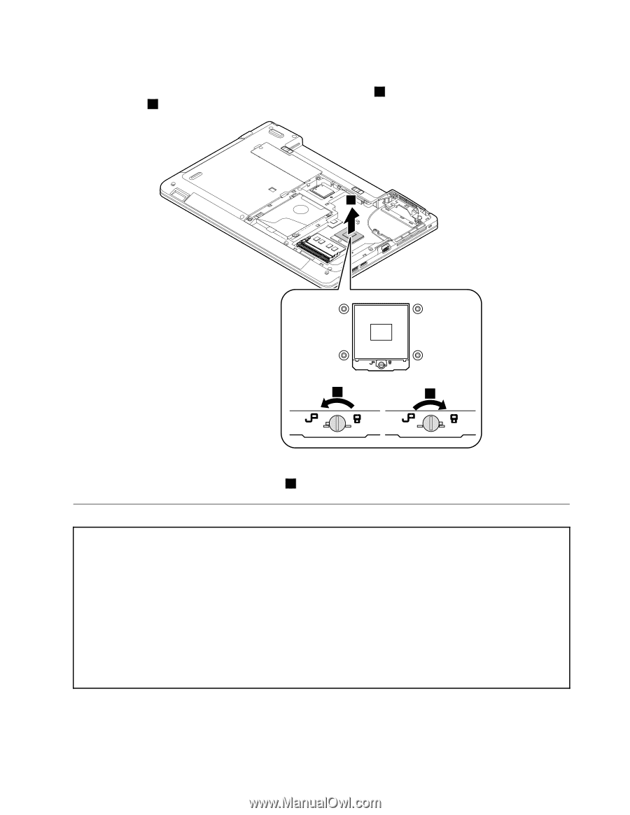
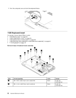
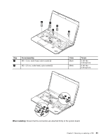
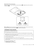
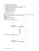
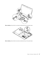
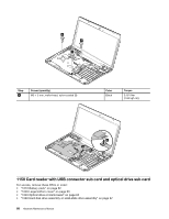
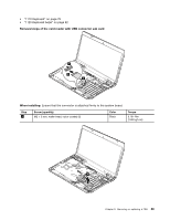
Removal steps of the microprocessor Rotate the head of the screw in the direction shown by the arrow 1 to release the lock; then remove the microprocessor 2 . 2 1 3 When installing: Place the microprocessor above the microprocessor socket, and then rotate the head of the screw in the direction shown by the arrow 3 to secure the microprocessor. 1140 System board assembly Important notices for handling the system board: When handling the system board, read the following: • The system board has an accelerometer, which can be broken when several thousands of G-forces are applied. Note: Dropping a system board from a height of as little as 6 inches so that it falls flat on a hard bench can subject the accelerometer to as much as 6000 G's of shock. • Be careful not to drop the system board on a bench top that has a hard surface, such as metal, wood, or composite. • Avoid rough handling of any kind. • At every point in the process, be sure not to drop or stack the system board. • If you put a system board down, be sure to put it only on a padded surface such as an ESD mat or a corrugated conductive surface. For access, remove these FRUs in order: • "1010 Battery pack" on page 62 • "1020 Large bottom cover" on page 63 Chapter 9. Removing or replacing a FRU 85
-
 1
1 -
2
-
3
-
4
-
5
-
6
-
7
-
8
-
9
-
10
-
11
-
12
-
13
-
14
-
15
-
16
-
17
-
18
-
19
-
20
-
21
-
22
-
23
-
24
-
25
-
26
-
27
-
28
-
29
-
30
-
31
-
32
-
33
-
34
-
35
-
36
-
37
-
38
-
39
-
40
-
41
-
42
-
43
-
44
-
45
-
46
-
47
-
48
-
49
-
50
-
51
-
52
-
53
-
54
-
55
-
56
-
57
-
58
-
59
-
60
-
61
-
62
-
63
-
64
-
65
-
66
-
67
-
68
-
69
-
70
-
71
-
72
-
73
-
74
-
75
-
76
-
77
-
78
-
79
-
80
-
81
-
82
-
83
-
84
-
85
-
 86
86 -
 87
87 -
 88
88 -
 89
89 -
 90
90 -
 91
91 -
 92
92 -
 93
93 -
 94
94 -
 95
95 -
 96
96 -
97
-
98
-
99
-
100
-
101
-
102
-
103
-
104
-
105
-
106
-
107
-
108
-
109
-
110
-
111
-
112
-
113
-
114
-
115
-
116
-
117
-
118
-
119
-
120
 |
 |