Lenovo ThinkPad R500 User Manual - Page 98
Close the LCD cover and turn the computer over. Then fasten the four screws, to secure the palm rest.
 |
View all Lenovo ThinkPad R500 manuals
Add to My Manuals
Save this manual to your list of manuals |
Page 98 highlights
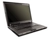
Table 12. Removal steps of palm rest (continued) 2. Attach the palm rest so that the two projections of the palm rest ( a ) firmly fit into the guide holes of the keyboard bezel as shown in this figure. a a 3. Push the front side of the palm rest until it clicks into place. 4. Close the LCD cover and turn the computer over. Then fasten the four screws to secure the palm rest. 90 ThinkPad R500 Hardware Maintenance Manual
-
 1
1 -
2
-
3
-
4
-
5
-
6
-
7
-
8
-
9
-
10
-
11
-
12
-
13
-
14
-
15
-
16
-
17
-
18
-
19
-
20
-
21
-
22
-
23
-
24
-
25
-
26
-
27
-
28
-
29
-
30
-
31
-
32
-
33
-
34
-
35
-
36
-
37
-
38
-
39
-
40
-
41
-
42
-
43
-
44
-
45
-
46
-
47
-
48
-
49
-
50
-
51
-
52
-
53
-
54
-
55
-
56
-
57
-
58
-
59
-
60
-
61
-
62
-
63
-
64
-
65
-
66
-
67
-
68
-
69
-
70
-
71
-
72
-
73
-
74
-
75
-
76
-
77
-
78
-
79
-
80
-
81
-
82
-
83
-
84
-
85
-
86
-
87
-
88
-
89
-
90
-
91
-
92
-
 93
93 -
 94
94 -
 95
95 -
 96
96 -
 97
97 -
 98
98 -
 99
99 -
 100
100 -
 101
101 -
 102
102 -
 103
103 -
104
-
105
-
106
-
107
-
108
-
109
-
110
-
111
-
112
-
113
-
114
-
115
-
116
-
117
-
118
-
119
-
120
-
121
-
122
-
123
-
124
-
125
-
126
-
127
-
128
-
129
-
130
-
131
-
132
-
133
-
134
-
135
-
136
-
137
-
138
-
139
-
140
-
141
-
142
-
143
-
144
-
145
-
146
-
147
-
148
-
149
-
150
-
151
-
152
-
153
-
154
-
155
-
156
-
157
-
158
-
159
-
160
-
161
-
162
-
163
-
164
-
165
-
166
-
167
-
168
-
169
-
170
-
171
-
172
-
173
-
174
-
175
-
176
-
177
-
178
-
179
-
180
-
181
-
182
-
183
-
184
-
185
-
186
-
187
-
188
-
189
-
190
-
191
-
192
-
193
-
194
-
195
-
196
-
197
-
198
-
199
-
200
-
201
-
202
-
203
-
204
-
205
-
206
-
207
-
208
-
209
-
210
-
211
-
212
-
213
-
214
-
215
-
216
-
217
-
218
-
219
-
220
-
221
-
222
-
223
-
224
-
225
-
226
 |
 |

Table 12. Removal steps of palm rest (continued)
2. Attach the palm rest so that the two projections of the palm rest (
±a²
) firmly
fit into the guide holes of the keyboard bezel as shown in this figure.
a
a
3. Push the front side of the palm rest until it clicks into place.
4. Close the LCD cover and turn the computer over. Then fasten the four screws
to secure the palm rest.
90
ThinkPad R500 Hardware Maintenance Manual