Lenovo ThinkPad R60e Hardware Maintenance Manual - Page 110
Controller
 |
View all Lenovo ThinkPad R60e manuals
Add to My Manuals
Save this manual to your list of manuals |
Page 110 highlights
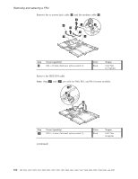
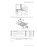
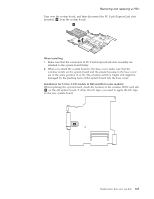
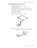
Removing and replacing a FRU Following components soldered on the top side of the system board are extremely sensitive. When you service the system board, avoid any kind of rough handling. a Accelerometer chip for the HDD Active Protection System™ b Security chip c CPU d Video chip e MCH (Memory Controller Hub) f ICH (I/O Controller Hub) c d e f b a 1 1 Step 1 Screw (quantity) M2 × 2.5 mm, flat-head, nylon-coated (2) (continued) Color Black Torque 0.167 Nm (1.7 kgfcm) 104 MT 0656, 0657, 0658, 0659, 9455, 9456, 9457, 9458, 9459, 9460, 9461, 9462, 9463, 9464, 8942, 8943, 8944, 8945, and 8947
-
 1
1 -
2
-
3
-
4
-
5
-
6
-
7
-
8
-
9
-
10
-
11
-
12
-
13
-
14
-
15
-
16
-
17
-
18
-
19
-
20
-
21
-
22
-
23
-
24
-
25
-
26
-
27
-
28
-
29
-
30
-
31
-
32
-
33
-
34
-
35
-
36
-
37
-
38
-
39
-
40
-
41
-
42
-
43
-
44
-
45
-
46
-
47
-
48
-
49
-
50
-
51
-
52
-
53
-
54
-
55
-
56
-
57
-
58
-
59
-
60
-
61
-
62
-
63
-
64
-
65
-
66
-
67
-
68
-
69
-
70
-
71
-
72
-
73
-
74
-
75
-
76
-
77
-
78
-
79
-
80
-
81
-
82
-
83
-
84
-
85
-
86
-
87
-
88
-
89
-
90
-
91
-
92
-
93
-
94
-
95
-
96
-
97
-
98
-
99
-
100
-
101
-
102
-
103
-
104
-
 105
105 -
 106
106 -
 107
107 -
 108
108 -
 109
109 -
 110
110 -
 111
111 -
 112
112 -
 113
113 -
 114
114 -
 115
115 -
116
-
117
-
118
-
119
-
120
-
121
-
122
-
123
-
124
-
125
-
126
-
127
-
128
-
129
-
130
-
131
-
132
-
133
-
134
-
135
-
136
-
137
-
138
-
139
-
140
-
141
-
142
-
143
-
144
-
145
-
146
-
147
-
148
-
149
-
150
-
151
-
152
-
153
-
154
-
155
-
156
-
157
-
158
-
159
-
160
-
161
-
162
-
163
-
164
-
165
-
166
-
167
-
168
-
169
-
170
-
171
-
172
-
173
-
174
-
175
-
176
-
177
-
178
-
179
-
180
-
181
-
182
-
183
-
184
-
185
-
186
-
187
-
188
-
189
-
190
-
191
-
192
-
193
-
194
-
195
-
196
-
197
-
198
-
199
-
200
-
201
-
202
-
203
-
204
-
205
-
206
-
207
-
208
-
209
-
210
-
211
-
212
-
213
-
214
-
215
-
216
-
217
-
218
-
219
-
220
-
221
-
222
-
223
-
224
-
225
-
226
-
227
-
228
-
229
-
230
-
231
-
232
-
233
-
234
-
235
-
236
-
237
-
238
-
239
-
240
-
241
-
242
-
243
-
244
 |
 |
Following
components
soldered
on
the
top
side
of
the
system
board
are
extremely
sensitive.
When
you
service
the
system
board,
avoid
any
kind
of
rough
handling.
±a²
Accelerometer
chip
for
the
HDD
Active
Protection
System
™
±b²
Security
chip
±c²
CPU
±d²
Video
chip
±e²
MCH
(Memory
Controller
Hub)
±f²
ICH
(I/O
Controller
Hub)
a
b
c
d
e
f
1
1
Step
Screw
(quantity)
Color
Torque
±1²
M2
×
2.5
mm,
flat-head,
nylon-coated
(2)
Black
0.167
Nm
(1.7
kgfcm)
(continued)
Removing
and
replacing
a
FRU
104
MT
0656,
0657,
0658,
0659,
9455,
9456,
9457,
9458,
9459,
9460,
9461,
9462,
9463,
9464,
8942,
8943,
8944,
8945,
and
8947