Lenovo ThinkPad T61 Hardware Maintenance Manual - Page 113
flat-head, nylon-coated, Silver, kgfcm
 |
View all Lenovo ThinkPad T61 manuals
Add to My Manuals
Save this manual to your list of manuals |
Page 113 highlights
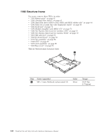
Following components soldered on the top side of the system board are extremely sensitive. When you service the system board, avoid any kind of rough handling. a Accelerometer chip for the HDD Active Protection System™ b Security chip c CPU d Video chip e MCH (Memory Controller Hub) f ICH (I/O Controller Hub) Bending or flexing the system board can cause ball grid array (BGA) connections to crack (unzip). c d e f b a Table 34. Removal steps of system board and PC Card/ExpressCard slots assembly 1 1 Step 1 Screw (quantity) M2 × 3 mm, flat-head, nylon-coated (2) Color Silver Torque 0.167 Nm (1.7 kgfcm) ThinkPad T61 and T61p (14.1-inch) 105
-
 1
1 -
2
-
3
-
4
-
5
-
6
-
7
-
8
-
9
-
10
-
11
-
12
-
13
-
14
-
15
-
16
-
17
-
18
-
19
-
20
-
21
-
22
-
23
-
24
-
25
-
26
-
27
-
28
-
29
-
30
-
31
-
32
-
33
-
34
-
35
-
36
-
37
-
38
-
39
-
40
-
41
-
42
-
43
-
44
-
45
-
46
-
47
-
48
-
49
-
50
-
51
-
52
-
53
-
54
-
55
-
56
-
57
-
58
-
59
-
60
-
61
-
62
-
63
-
64
-
65
-
66
-
67
-
68
-
69
-
70
-
71
-
72
-
73
-
74
-
75
-
76
-
77
-
78
-
79
-
80
-
81
-
82
-
83
-
84
-
85
-
86
-
87
-
88
-
89
-
90
-
91
-
92
-
93
-
94
-
95
-
96
-
97
-
98
-
99
-
100
-
101
-
102
-
103
-
104
-
105
-
106
-
107
-
 108
108 -
 109
109 -
 110
110 -
 111
111 -
 112
112 -
 113
113 -
 114
114 -
 115
115 -
 116
116 -
 117
117 -
 118
118 -
119
-
120
-
121
-
122
-
123
-
124
-
125
-
126
-
127
-
128
-
129
-
130
-
131
-
132
-
133
-
134
-
135
-
136
-
137
-
138
-
139
-
140
-
141
-
142
-
143
-
144
-
145
-
146
-
147
-
148
-
149
-
150
-
151
-
152
-
153
-
154
-
155
-
156
-
157
-
158
-
159
-
160
-
161
-
162
-
163
-
164
-
165
-
166
-
167
-
168
-
169
-
170
-
171
-
172
-
173
-
174
-
175
-
176
-
177
-
178
 |
 |

Table
34.
Removal
steps
of
system
board
and
PC
Card/ExpressCard
slots
assembly
1
1
Step
Screw
(quantity)
Color
Torque
±1²
M2
×
3
mm,
flat-head,
nylon-coated
(2)
Silver
0.167
Nm
(1.7
kgfcm)
Following
components
soldered
on
the
top
side
of
the
system
board
are
extremely
sensitive.
When
you
service
the
system
board,
avoid
any
kind
of
rough
handling.
±a²
Accelerometer
chip
for
the
HDD
Active
Protection
System
™
±b²
Security
chip
±c²
CPU
±d²
Video
chip
±e²
MCH
(Memory
Controller
Hub)
±f²
ICH
(I/O
Controller
Hub)
Bending
or
flexing
the
system
board
can
cause
ball
grid
array
(BGA)
connections
to
crack
(unzip).
a
b
c
d
e
f
ThinkPad
T61
and
T61p
(14.1-inch)
105