Lenovo U31-70 Laptop Hardware Maintenance Manual - Lenovo U31-70 - Page 60
do not pinch the antenna cables when you attach the LCD assembly. Route
 |
View all Lenovo U31-70 Laptop manuals
Add to My Manuals
Save this manual to your list of manuals |
Page 60 highlights
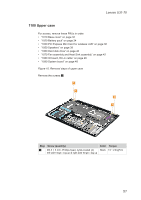
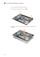
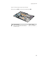
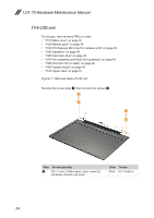
U31-70 Hardware Maintenance Manual Figure 11. Removal steps of LCD unit (continued) Detach the camera connector in the direction shown by arrow 7. 7 Remove the LCD cable in the direction shown by arrows 8. 8 8 When installing: Make sure that the connector is attached firmly and that you do not pinch the antenna cables when you attach the LCD assembly. Route the LCD cable along the cable guides. 56
-
 1
1 -
2
-
3
-
4
-
5
-
6
-
7
-
8
-
9
-
10
-
11
-
12
-
13
-
14
-
15
-
16
-
17
-
18
-
19
-
20
-
21
-
22
-
23
-
24
-
25
-
26
-
27
-
28
-
29
-
30
-
31
-
32
-
33
-
34
-
35
-
36
-
37
-
38
-
39
-
40
-
41
-
42
-
43
-
44
-
45
-
46
-
47
-
48
-
49
-
50
-
51
-
52
-
53
-
54
-
 55
55 -
 56
56 -
 57
57 -
 58
58 -
 59
59 -
 60
60 -
 61
61 -
 62
62 -
 63
63 -
 64
64 -
 65
65 -
66
-
67
-
68
-
69
-
70
-
71
-
72
-
73
-
74
-
75
-
76
-
77
-
78
-
79
-
80
 |
 |

56
U31-70 Hardware Maintenance Manual
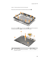
Figure 11. Removal steps of LCD unit
(continued)
Detach the camera connector in the direction shown by arrow
7
.
7
Remove the LCD cable in the direction shown by arrows
8
.
8
8
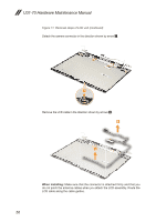
When installing:
Make sure that the connector is attached firmly and that you
do not pinch the antenna cables when you attach the LCD assembly. Route the
LCD cable along the cable guides.