Lenovo V470 Hardware Maintenance Manual - Page 60
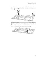
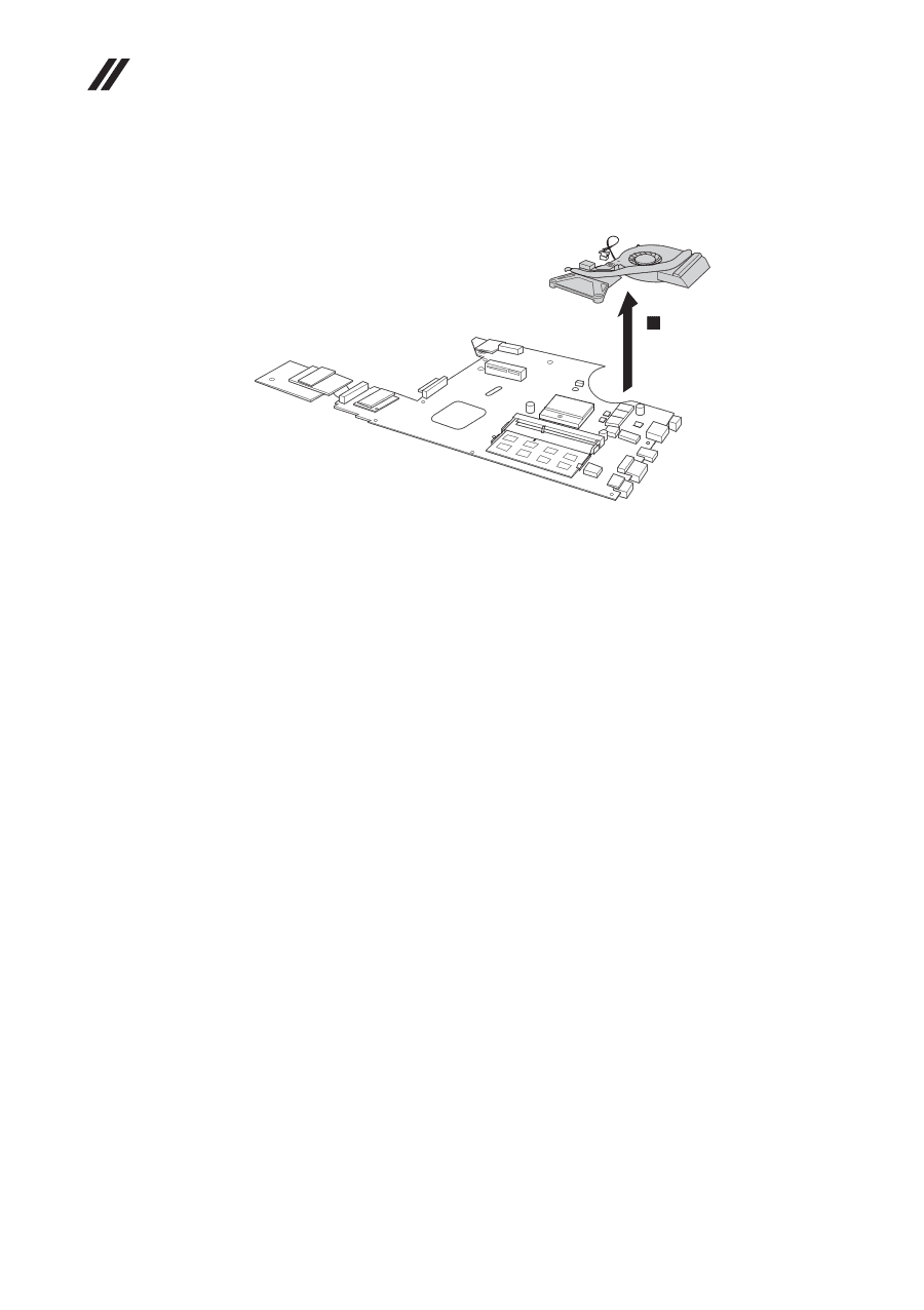
Lift the fan assembly and heat sink assembly in the direction shown by arrow
 |
View all Lenovo V470 manuals
Add to My Manuals
Save this manual to your list of manuals |
Page 60 highlights
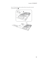
Lenovo V470/B470 Hardware Maintenance Manual Figure 12. Removal steps of fan assembly and heat sink assembly (continued) Lift the fan assembly and heat sink assembly in the direction shown by arrow c. Be careful not to damage the connector. 3 56
-
 1
1 -
2
-
3
-
4
-
5
-
6
-
7
-
8
-
9
-
10
-
11
-
12
-
13
-
14
-
15
-
16
-
17
-
18
-
19
-
20
-
21
-
22
-
23
-
24
-
25
-
26
-
27
-
28
-
29
-
30
-
31
-
32
-
33
-
34
-
35
-
36
-
37
-
38
-
39
-
40
-
41
-
42
-
43
-
44
-
45
-
46
-
47
-
48
-
49
-
50
-
51
-
52
-
53
-
54
-
 55
55 -
 56
56 -
 57
57 -
 58
58 -
 59
59 -
 60
60 -
 61
61 -
 62
62 -
 63
63 -
 64
64 -
 65
65 -
66
-
67
-
68
-
69
-
70
-
71
-
72
-
73
-
74
-
75
-
76
-
77
-
78
-
79
-
80
-
81
-
82
-
83
-
84
-
85
-
86
-
87
-
88
-
89
-
90
-
91
 |
 |
Lenovo V470/B470 Hardware Maintenance Manual
56
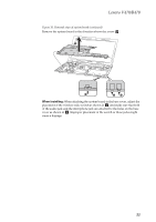
Figure 12. Removal steps of fan assembly and heat sink assembly (continued)
Lift the fan assembly and heat sink assembly in the direction shown by arrow
. Be careful not to damage the connector.
c
3